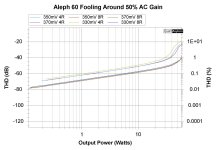
After a delay working on another project ... at long last I finally had a chance to get back to my Aleph 60 for a little while. It's still not done... but I wanted to do a few measurements before I buttoned it up. These are (as the title in a few of the graphs say) playing around. I don't even remember the bias I originally set. I just got it hot...
The AC Gain is 50% by the method described in the guide. For those that like measurements... here ya go! I thought it was pretty cool that the 1% distortion point was... you guessed it ... 60W (8R).
Note... I am just getting familiar with measurements. So, take these with a bucket of salt. They make sense, so I'm posting them. I also ensured a high level of repeatability. I trust them, but ... you may not. If I find any errors as I learn more, I'll certainly say something. tl;dr - they're correct to the best of my knowledge and ability.
I am tickled to death with the "Wretched Excess" PSU and the A60. I had to "go deep" to try and find any 60Hz and harmonics. It's quiet.
In no particular order.... Thank you to:
@rhthatcher - You DA MAN!
@Extreme_Boky and @TungstenAudio - I took all the teachings to heart. I am still not sure that I completely understand it all ...
@Zen Mod the Mighty and the ever-guiding and kind @6L6 for keeping a fella like me between the ditches...
@Ben Mah and @Dennis Hui for measurement guidance and just being awesome.
Last, but not least - @Nelson Pass -
I'm sure I've unintentionally left someone out. Apologies. I've been inspired (stolen ideas shamelessly) from so many people.
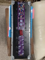
I'll post pics once I've done some prettying up. The last pics posted are pretty much the way it still looks.
And... the best measurement of all... it sounds awesome!
I still want to play with AC gain etc... but that will come later.
Here's the noise floor. Yep... it's quiet...
View attachment 1215032
Here's the Power vs THD...
View attachment 1215037
Some 8R distortion measurements. The 2nd Harmonic (negative) is prevalent throughout the power range.
View attachment 1215039 View attachment 1215040 View attachment 1215041 View attachment 1215042 View attachment 1215043
And a few at 4R
View attachment 1215050 View attachment 1215051 View attachment 1215052 View attachment 1215053 View attachment 1215054
More to come... I've had a blast building and learning as I go with this project.
Thanks to all!


Look at you reaching for the sky. Well done!
What do you mean by push?
Boyz, what's few % of difference between friends?
Anyhow - no one is taking Aleph, to squeeze last ounce of juice from it

^ 
I'm grinning from ear to ear...
I'm grinning from ear to ear...
And... the best measurement of all... it sounds awesome!
What do you mean by push? I didn't take it to 100W
Post Title: How to make Kosher Aleph 60
now I see what you have as "Aleph 60"
to have exact one ( and most importantly- declared power @4R load) we need to know few things:
@8R, power envelope for Aleph is limited with voltage envelope- meaning rails
@4R and lower, power envelope for Aleph is limited with current envelope - set by Iq and overall current capability of OS
what I see as difference to original and its dream figure of 100W@4R@1% is simply number of output mosfets (in current arrangement)
to get there, resulting xconductance (dictated by type of mosfets used,value of source resistors and sum number of mosfets) must be equal to original
Aleph 60 is having 6 mosfets up, and 6 mosfets down, sum being 12 mosfets per channel
original IRF244, xconductance close to IRFP240
original source resistors - 1R/3W MOX
but - having place for 4+4 mosfets on your pcb ........................ scenario for making Aleph 60 of it is simple:
instead of IRFP240 (noted in build docs) take IRFP150 (double die IRFP240, thus double xconductance), decrease all source resistors to 0R47; so - at least 3pcs up and 3pcs down, but - heck - populate all 4up and all 4 down
set sum Iq must be in range of 2A5 (number noted in Papa's SM, ignore lower meaning 370mV@1R source resistor; calc sez that 2A5 Iq sits better with declared amp dissipation number)
sum value of paralleled resistors in output sense group - same as in original Aleph 60 (1/6R=0R166)
that way you'll get same or better(if you use 4+4) current capability of OS as in targeted Aleph 60 and reach dream figure of 100W@4R
don't despair - decade ago I helped my dear AR2 to solve a puzzle why his DIY X600 is not having nearly 50% of power; when I realized that DIY X600 package he got from someone is having 1/3 of original number of mosfets, problem was solved

edit: now, when I gave you cheerful and free recipe how to solve missing power case, just to inform you that I bought World's Stash of IRFP150, and that you can have matched quartets only from me, price being measly 258$/quartet
matching made only by night, first quarter of moon, and I was strictly in Virgo mood

Attachments
Last edited:
main question - how on earth you guys think to cool that, one channel being situated on one side/heatsink?
meaning - how big that case/heatsink must be?
edit: for clarity - original Aleph 60 had half mosfet bank (6pcs) on one side/heatsink, second half mosfet bank (6pcs) on other side/heatsink
being there, done that - made my self bunch of never-ending problems (not aware of some important fact just lead to never-ending chain of applied patches for resulting problems) - as Casey did say to my Kid Vale - "Your ambition outweighed your talent"
Luckily - "Talent" is thing which can be polished with efforts and mileage
Last edited:
Yep... all kosher so far.... 12 per side ... same same.Post Title: How to make Kosher Aleph 60
now I see what you have as "Aleph 60"
to have exact one ( and most importantly- declared power @4R load) we need to know few things:
@8R, power envelope for Aleph is limited with voltage envelope- meaning rails
@4R and lower, power envelope for Aleph is limited with current envelope - set by Iq and overall current capability of OS
what I see as difference to original and its dream figure of 100W@4R@1% is simply number of output mosfets (in current arrangement)
to get there, resulting xconductance (dictated by type of mosfets used,value of source resistors and sum number of mosfets) must be equal to original
Aleph 60 is having 6 mosfets up, and 6 mosfets down, sum being 12 mosfets per channel
Awesomeoriginal IRF244, xconductance close to IRFP240
Sameoriginal source resistors - 1R/3W MOX
See the "add-on" board and pic below.... 6 + 6but - having place for 4+4 mosfets on your pcb ........................ scenario for making Aleph 60 of it is simple:
Edited to add - Same... 370mV ... after running attached, I may back off to 350mV for MY build... Just to have it run a little cooler with again... FOR ME... no loss in what I need. Sinks are at 58C in 23C room at 370mV. A little cooler would be nice. May use babysitter.instead of IRFP240 (noted in build docs) take IRFP150 (double die IRFP240, thus double xconductance), decrease all source resistors to 0R47; so - at least 3pcs up and 3pcs down, but - heck - populate all 4up and all 4 down
set sum Iq must be in range of 2A5 (number noted in Papa's SM, ignore lower meaning 370mV@1R source resistor; calc sez that 2A5 Iq sits better with declared amp dissipation number)
fortunately, I have somewhere between a butt-ton and a metric $hit-tonne of 150s.sum value of paralleled resistors in output sense group - same as in original Aleph 60 (1/6R=0R166)
that way you'll get same or better(if you use 4+4) current capability of OS as in targeted Aleph 60 and reach dream figure of 100W@4R
don't despair - decade ago I helped my dear AR2 to solve a puzzle why his DIY X600 is not having nearly 50% of power; when I realized that DIY X600 package he got from someone is having 1/3 of original number of mosfets, problem was solved
edit: now, when I gave you cheerful and free recipe how to solve missing power case, just to inform you that I bought World's Stash of IRFP150, and that you can have matched quartets only from me, price being measly 258$/quartet
matching made only by night, first quarter of moon, and I was strictly in Virgo mood
")
In all seriousness I have no desire whatsoever to push MY build of the Aleph 60 any further. I was just answering the question asked by Tony. HE may want HIS build to be 100W at 1% into 4R. Mine... just... won't... be... set... up... that way...
Edited to add... Sorry to have answered Tony's question a bit sheepishly. I'll say this. If anyone using Randy's boards and the schematic and settings in the guide can achieve 100W 4R 1%, I will PayPal them $100USD F&F. Must post verified proof. If anyone has a "Real" Aleph 60 that has been measured.... and will post the results... I will PayPal them $50USD. Then, all of this can go away. I just want to enjoy my amplifier.
This isn't about my amp! I love the thing, and I'm not changing it (except to maybe play with the AC gain for fun). It has PLENTY of power for my needs.
Attachments
Last edited:
OK, my bad (and I'm glad for that) - now I see that you guys thought of thermal arrangement ........... beat me, now I see that I read wrong building guide for aleph 60 - didn't got to end of document showing additional board
ignore thermal management rant above - I was most laughing at my self, remembering all mistakes I made in past
so, IAIMH - you have 6+6 mosfets and there still no 100W@4R
then all I can see as reason for not getting to full power is either Aleph CCS AC gain not being same as Papa's, or PSU defficiency
my peanut working as that
will think further, maybe fire sim to ease Geezer cells
^ Not a worry in the world. You're amazing. As mentioned... and I hope my post did not come off as a rant... I LOVE this amplifier. I personally have no desire whatsoever to try to get 100W (at any distortion level) into 4R.
With that said... if people trust my (lack of) skills... I'd be thrilled to try a few things re: CCS AC gain if they're easy enough to implement. You know... (imitating Sally Struthers) for the children.
This will all happen after I get back from vacation...
Laissez les bons temps rouler

With that said... if people trust my (lack of) skills... I'd be thrilled to try a few things re: CCS AC gain if they're easy enough to implement. You know... (imitating Sally Struthers) for the children.
This will all happen after I get back from vacation...
Laissez les bons temps rouler
as I see it, Aleph CCS AC gain is approx. 65%, whichever way you're measuring it
simplest for me to present is - ratio of (Vac across one source resistor in Aleph CCS * number of outputs in Aleph CCS) / (Vac across sense resistor group)
moderate level of power, dummy load connected
that practically showing % of current contribution of Aleph CCS in sum output current
pretty much same results as Papa's way of measuring it
there are other ways, but this is simplest to my brain
figure of 65% got from ancient sim note I made (and just found); sim is good enough for simple fact as that
edit - line-up of bracketed things corrected
Last edited:
After a couple months of separation from the Aleph 60 monoblocks I built last year (Randy's boards in the 3 up 3 down each side of the "monoblock chassis"), time I spent listening to many different M2X daughter boards, tweaking the F5 turbo V2's distortion characteristic by ear and voltmeter, a vintage Denon integrated's pre-in, and even an Aleph ~20 in balanced input (thanks Balanced Iron Pre!) (2 up, 2 down per channel in a 4U-300 chassis), I hooked up the A60 monoblocks again last night.
It's like slipping on an old pair of jeans. Oh, yeah. Perfect. There's just so much more there there, even cold. What a hobby! What a project and gift from Papa and Randy for these boards and power supply boards and matched mosfets.
It's like slipping on an old pair of jeans. Oh, yeah. Perfect. There's just so much more there there, even cold. What a hobby! What a project and gift from Papa and Randy for these boards and power supply boards and matched mosfets.
^ It is soooooooo wonderful ain't it?!
Attached for fun and for only fun... super duper duper quick fun. I will PayPal myself. Don't need original A60 measurements. But... if someone wants to post, they can.... just no $$ from me.
I did it... for the children... LOL!
Attached for fun and for only fun... super duper duper quick fun. I will PayPal myself.
Don't need original A60 measurements. But... if someone wants to post, they can.... just no $$ from me.I did it... for the children... LOL!
Attachments
Just to be sure I don’t cause even more confusion
it seems you did
max power at 4R should be with maxed Aleph CCS AC gain
please - measure and calc AC gain either with Pa's procedure or as I wrote in
simplest for me to present is - ratio of (Vac across one source resistor in Aleph CCS * number of outputs in Aleph CCS) / (Vac across sense resistor group)
you really need just two Vac meters clipped in to set that on the fly
I'm adding the Aleph 60 using IRFP150's to my project queue.
I have an ebay chassis with massive heatsinks that is a perfect candidate. Looking at my current project list, this will get done sometime in spring 2024... Plethora of Pinjatas will come before A60/IRFP150
Thank you for the inspiration on this one @Zen Mod
I have an ebay chassis with massive heatsinks that is a perfect candidate. Looking at my current project list, this will get done sometime in spring 2024... Plethora of Pinjatas will come before A60/IRFP150
Thank you for the inspiration on this one @Zen Mod
@Zen Mod - any other stuff will have to wait a week. I’m out of “the office”.
See Randy’s guide and schematics for measurement points and process. It’s easy peasy.
My purpose was to show 100W 4R … numbers on how the numbers are calculated are meaningless to me. I explained how I did it… with Randy’s excellent guide … so people can replicate it.
25% 50% 10000000% all irrelevant.
@rhthatcher -
If you have a sec… for the nightly ZM. I can’t get to the guide with the math at the moment, and I’m typing with my thumbs on a tiny screen.
The measurements were super easy as you intended
200mV was measured across appropriate resistor with jumper off signal in, amp loaded 8R.
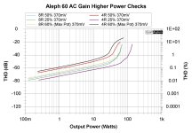
% I put in chart was the value dialed in with the jumper back on across same resistor.
So wherever your process says 50% sub in the value I put in the chart…
If you have a way to get to whatever calculation ZM wants before I’m back in town, that’d be great.
It couldn’t hurt for me to replicate the test anyway… who knows what I screwed up…
If you have a sec… for the nightly ZM. I can’t get to the guide with the math at the moment, and I’m typing with my thumbs on a tiny screen.
The measurements were super easy as you intended
200mV was measured across appropriate resistor with jumper off signal in, amp loaded 8R.
% I put in chart was the value dialed in with the jumper back on across same resistor.
So wherever your process says 50% sub in the value I put in the chart…
If you have a way to get to whatever calculation ZM wants before I’m back in town, that’d be great.
It couldn’t hurt for me to replicate the test anyway… who knows what I screwed up…
looking at graph you posted (#953), for me is puzzling that violet trace (lowest THD while furthest with power on 4R) is with smallest Aleph CCS AC gain
while, for my peanut brain, it should be for highest Aleph CCS AC gain
again, how I'm grasping Pa's nomenclature:
if output current swing is 1A, contribution of lower amp half is 0.5A and contribution of upper amp half is 0.5A, that means that Aleph CCS (upper half) AC gain is 50%
if output current swing is 1A, contribution of lower amp half is 0.35A and contribution of upper amp half is 0.65A, that means that Aleph CCS (upper half) AC gain is 65%
if output current swing is 1A, contribution of lower amp half is 0.65A and contribution of upper amp half is 0.35A, that means that Aleph CCS (upper half) AC gain is 35%
simple as that
what is slightly confusing, as term - without really grasping entire Papa's procedure is that "gain" is used instead of "contribution", with number expressed either as percentage or as something lower than 1, where 1 as one whole is sum current output of amp
Last edited:
- Home
- Amplifiers
- Pass Labs
- Classic Aleph Amplifier for Modern UMS Chassis Builder's Thread