I didn't think a horn that tall would fit under the dash of most cars and be easy to drive.
How high are you trying to go with this horn? Seems like you would want a supertweeter on the topend. Tall horns in a car have poor treble response. Another reason that I am asking if strictly midrange, the foam may or may not benefit greatly. I would guess in the 4-6k range is helped the most with the foam.
I've put the foam in half a dozen different horns now. With an oblate spheroidal waveguide the difference was the least noticeable; with the horn on the drivers side the difference is the most noticeable, by far.
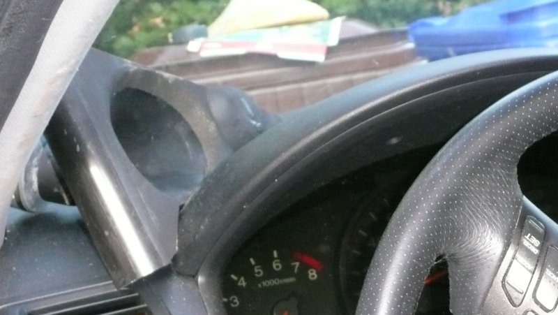
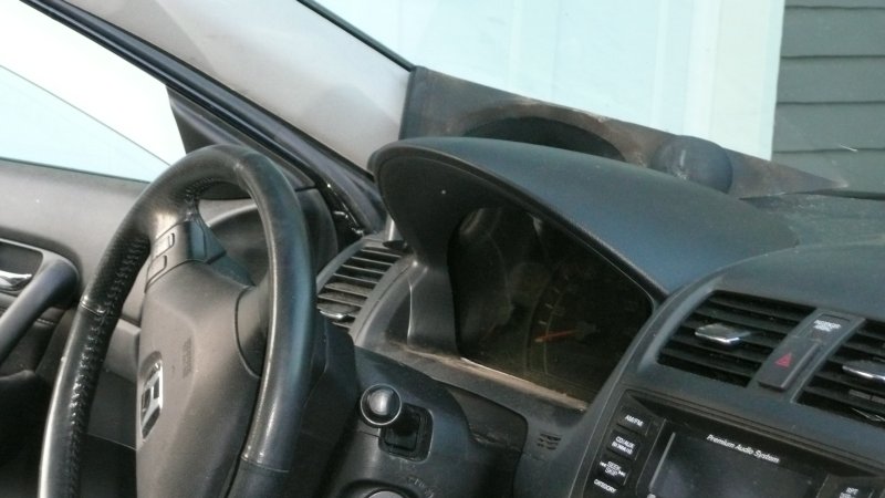
Subjectively, the horn on the driver's side is benefitting more from the foam than the horn on the passenger side. My hypothesis is that this is due to the throat being way off center on the drivers side, and much closer to center on the passenger's side.
If you compare the two, you'll notice that the throat on the driver's side is 2-3" off center.
Since the foam absorbs reflections inside the horn, and most of the reflections are at the throat and the mouth, the driver's side horn would be expected to have more reflections. (since it's further off center.)
Or at least that's my hunch.
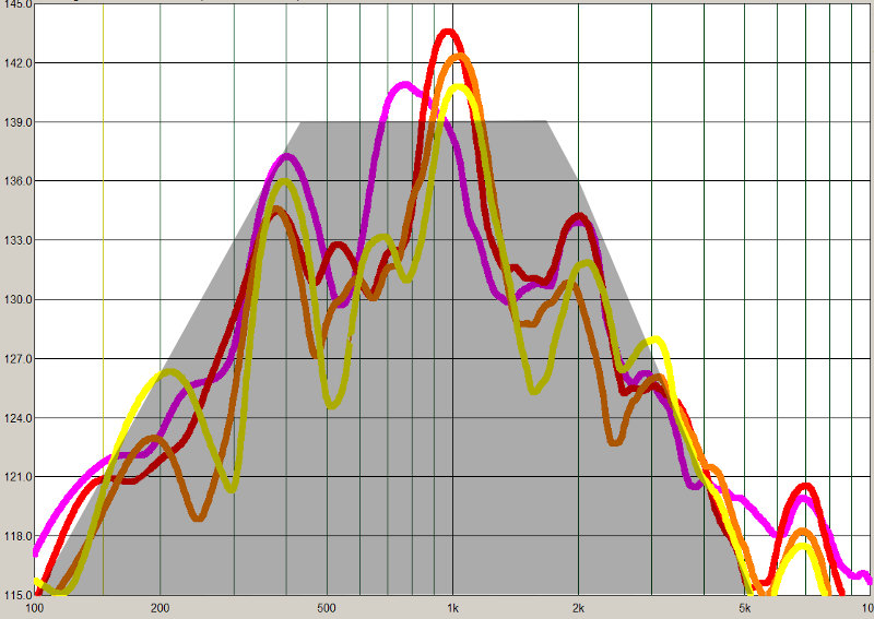
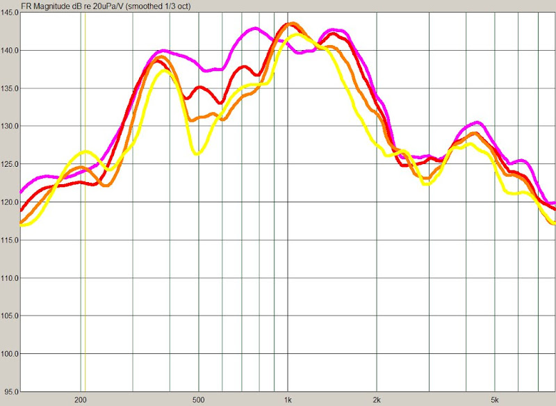
Last week I was getting really frustrated with the frequency response of the new horns. Here's the response of the horn last week; you'll note that there's a hole at 500hz and a peak at 1khz. This will be very difficult to fix with EQ, due to the proximity between the two.
Here's the response graph:
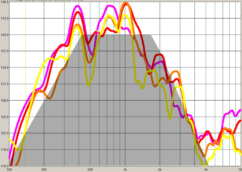
Here's the response graph of the *other* horn, measured from the passenger's side. The response shows similar problems.
Out of sheer frustration, I tried a few things:
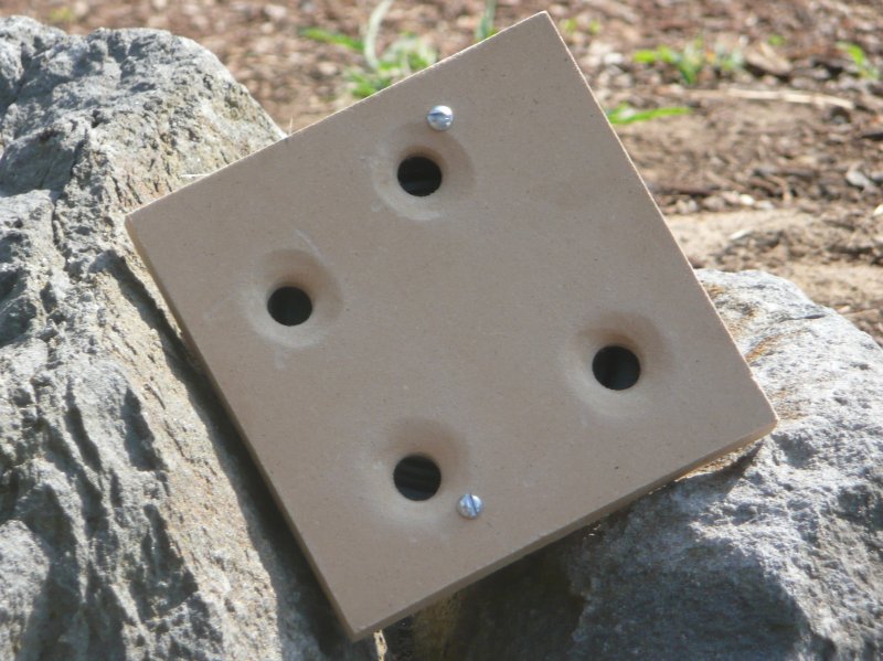
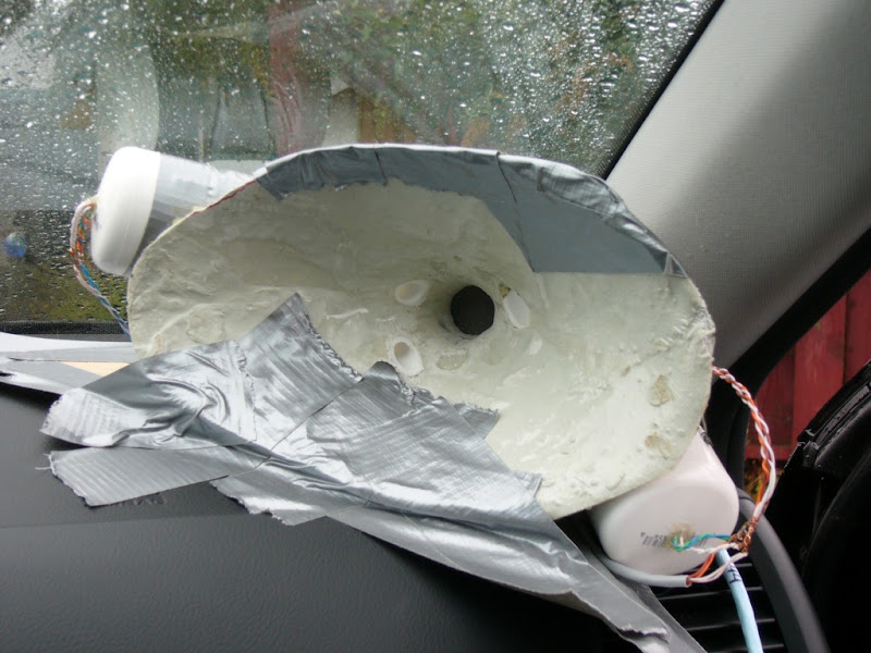
Once none of that fixed things, I started trying some real crazy stuff. First I built a bandpass box for the midrange, to see if it would measure flatter than the horn.
Here's what the box looks like:
And here's the frequency response of the bandpass box, tucked under the dash.
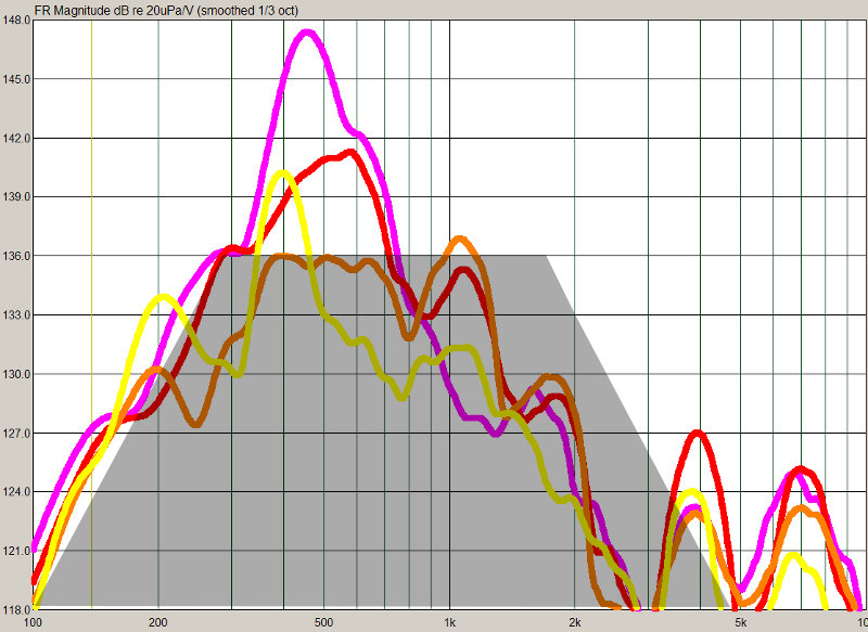
The grey area is the target response.
You can see here that the response of my horns have some issues, but the bandpass is even worse. The purple curve is on-axis, and has an 8db peak at 500hz. The worst part about this measurement isn't the frequency response, it's the polar response. The polar response varys wildly below 1500hz. Above 1500hz the frequency response is terrible, but at least the polar response is consistent.
Due to the abominal polar response, this enclosure won't image well at all.
I also tried a "conventional" enclosure. The polar response of a conventional enclosure in the car was even worse than the bandpass AND the horn.
This is the challenge of getting a good image in a car. Any speaker that's bigger than 3" or so is going to have terrible polar response, due to reflections. But horns are difficult to get right, because we don't have enough room for one that's properly sized.
All is not lost though...
I solved the problem with the horns over the weekend. It literally took the ENTIRE weekend, but I solved it. Here's a hint. Look at the response of the left and right horn, and you'll notice there's a difference. That difference is what clued me into the flaw in my horns.
Stay tuned..
Here's the response graph:
Here's the response graph of the *other* horn, measured from the passenger's side. The response shows similar problems.
Out of sheer frustration, I tried a few things:
- Stuffed foam blocks into the horn, to see if it would eliminate the peaks and dips
- Added a roundover UNDER the horn. While it didn't improve the on-axis frequency response, it DID improve the polar response. I'll dive into that in the next few days.
- Put foam in the horn. Same results as above, the polar response improved, but there's little change in on-axis frequency response.
Once none of that fixed things, I started trying some real crazy stuff. First I built a bandpass box for the midrange, to see if it would measure flatter than the horn.
Here's what the box looks like:
And here's the frequency response of the bandpass box, tucked under the dash.
The grey area is the target response.
You can see here that the response of my horns have some issues, but the bandpass is even worse. The purple curve is on-axis, and has an 8db peak at 500hz. The worst part about this measurement isn't the frequency response, it's the polar response. The polar response varys wildly below 1500hz. Above 1500hz the frequency response is terrible, but at least the polar response is consistent.
Due to the abominal polar response, this enclosure won't image well at all.
I also tried a "conventional" enclosure. The polar response of a conventional enclosure in the car was even worse than the bandpass AND the horn.
This is the challenge of getting a good image in a car. Any speaker that's bigger than 3" or so is going to have terrible polar response, due to reflections. But horns are difficult to get right, because we don't have enough room for one that's properly sized.
All is not lost though...
I solved the problem with the horns over the weekend. It literally took the ENTIRE weekend, but I solved it. Here's a hint. Look at the response of the left and right horn, and you'll notice there's a difference. That difference is what clued me into the flaw in my horns.
Stay tuned..
In the last post I noted that I was getting extremely frustrated with the measured response of the horns. Particularly due to a dip at 500hz, coupled with a peak at 1khz. Over the weekend I stumbled across the problem. It wasn't a reflection, or a problem with the dimensions. The horn itself was buzzing. I was listening to music over them, and happened to notice that the horns sounded better if I literally pushed against them.
My theory is that physically pressing against the horn made it more rigid.
So I spent the whole weekend going crazy with cross braces, constrained layer damping, and even braces right THROUGH the horn.
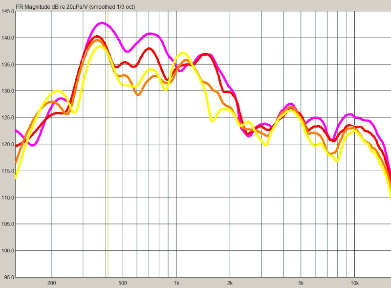
The measurements confirm my suspicions; both the peak and the dip are significantly reduced.
Even better, the roundover on the horn improved the directivity. This means that a bit of EQ will smooth out the response on AND off axis.
(EQ is most effective when the directivity is constant; otherwise the speaker is only flat on ONE axis, and the reflected energy isn't consistent with what you hear on-axis. Basically the speaker sounds odd if this pre-req isn't met, and it won't image.)
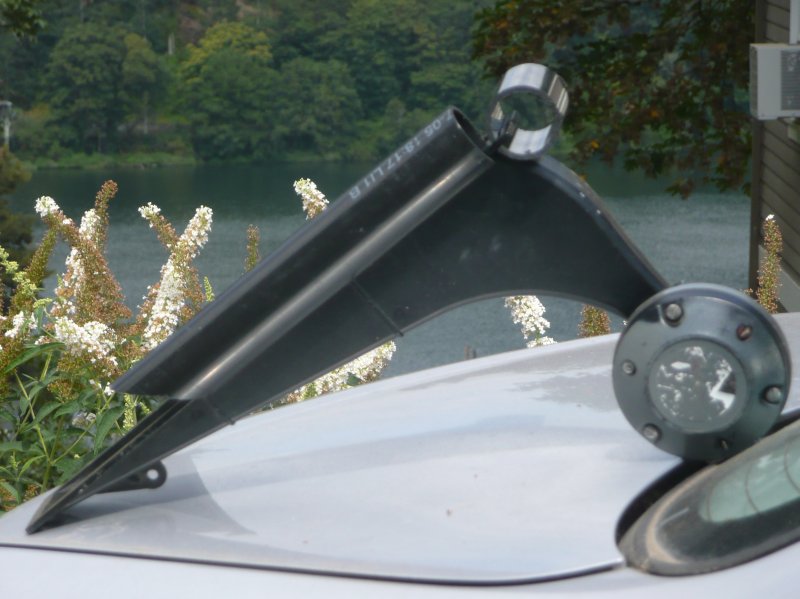
Anyways, here's some pics of the new and improved horns. I've also included pics of the USD waveguides, for comparisons sake. The USD waveguides have a roundover at the moment too. I measured them and found the roundover made a huge improvement.
I will post measurements of the improved horn, along with measurements of the USD waveguide, shortly.
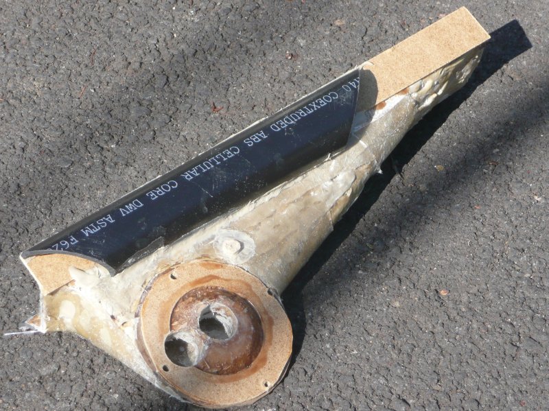
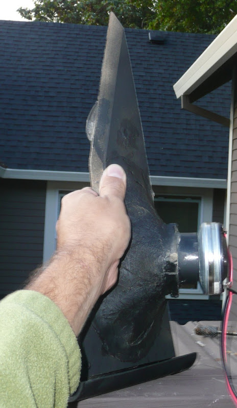
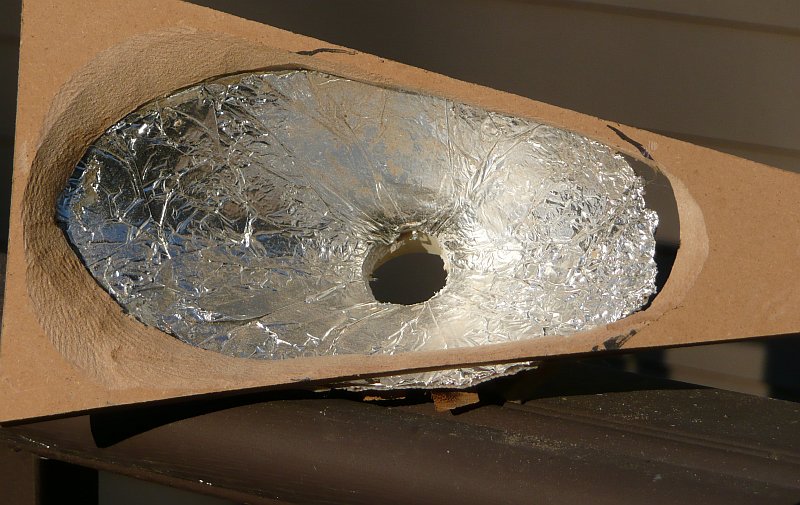
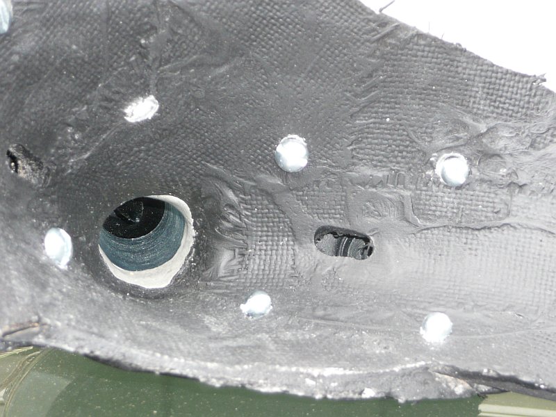
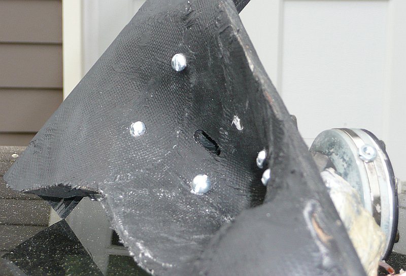
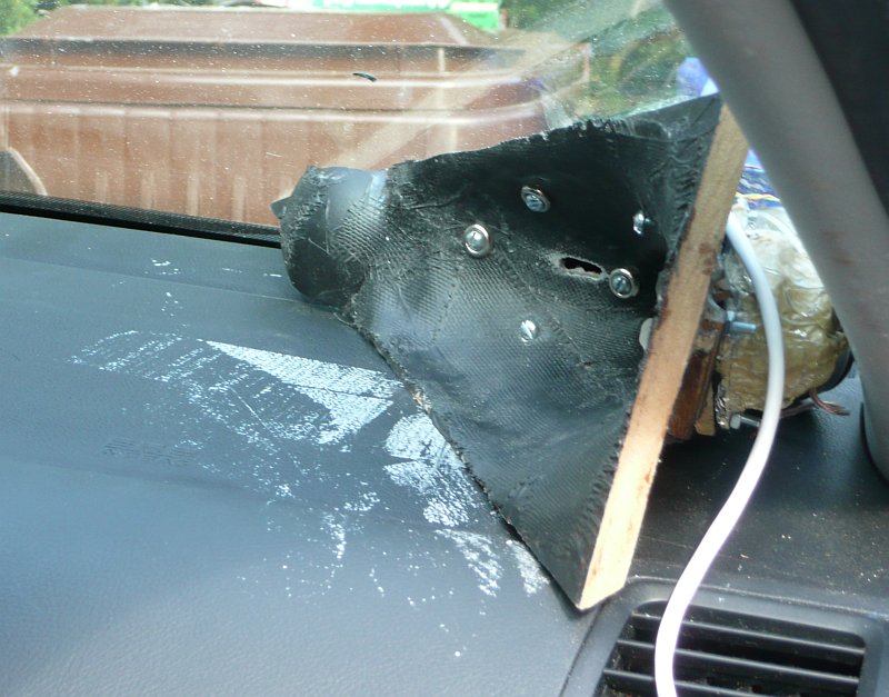
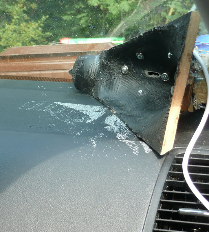
Note there's a brace right THROUGH the horn now, I've added a layer of glass with a sandwich of clay and liquid nails in the center, and there's a roundover now.
It's not pretty, but it's going to be wrapped in grill cloth when I'm finished. All of this will be under the dash. The roundover and the braces helped a LOT.
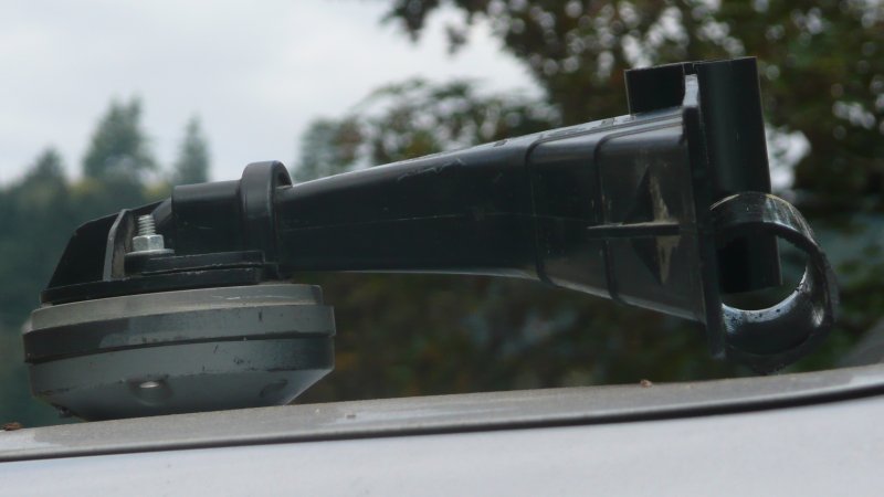
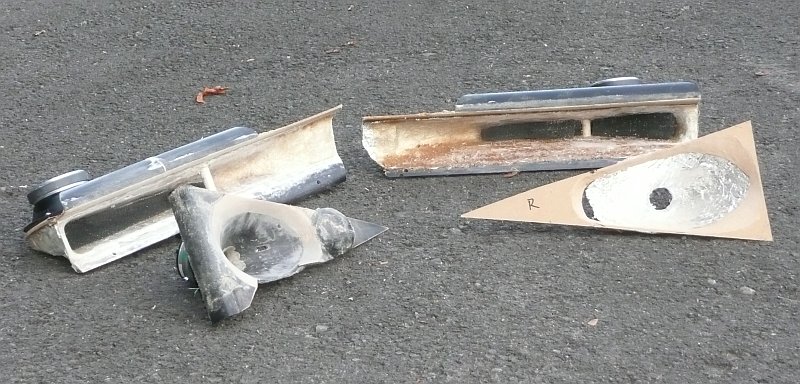
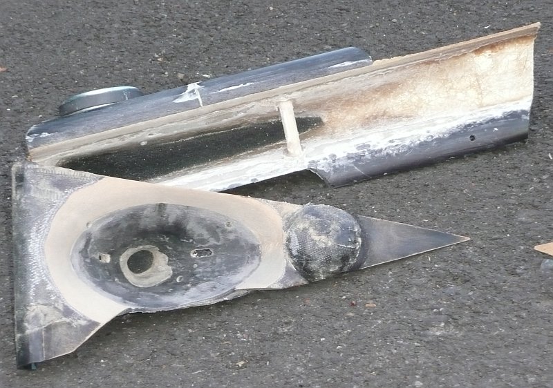
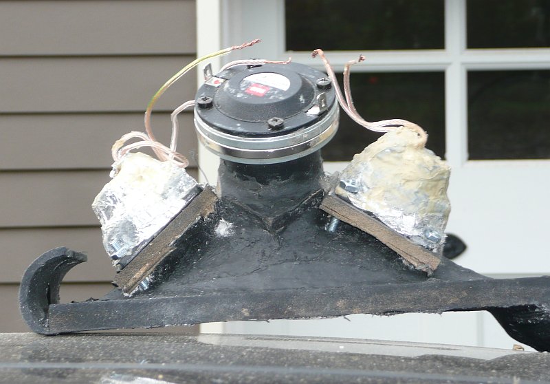
Side view of USD waveguide
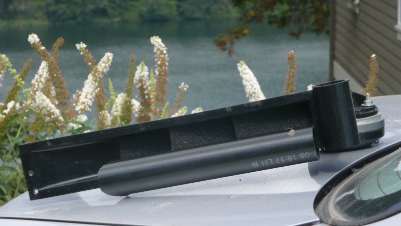
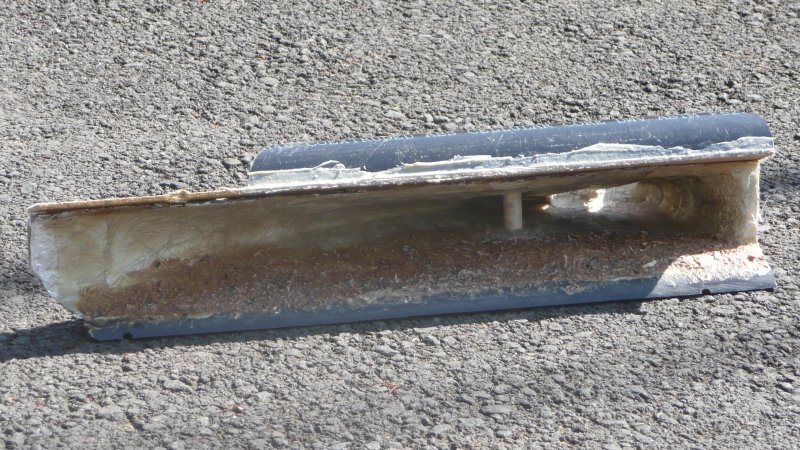
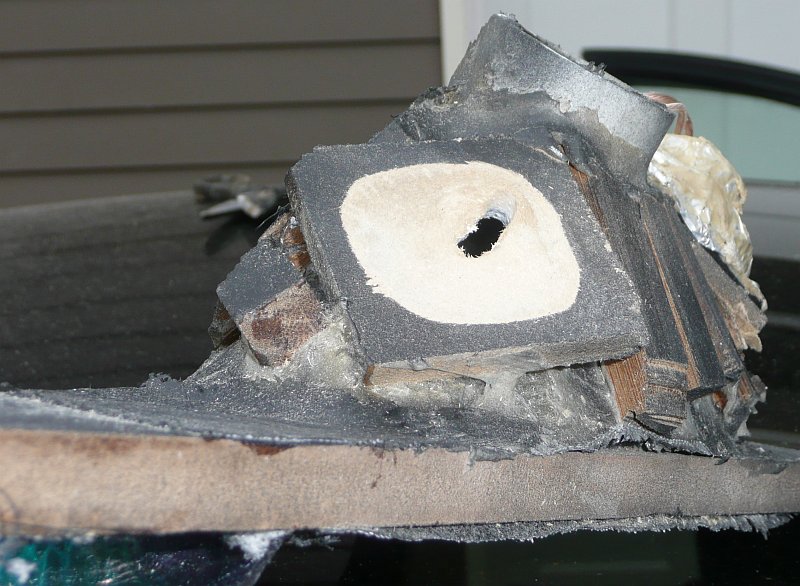
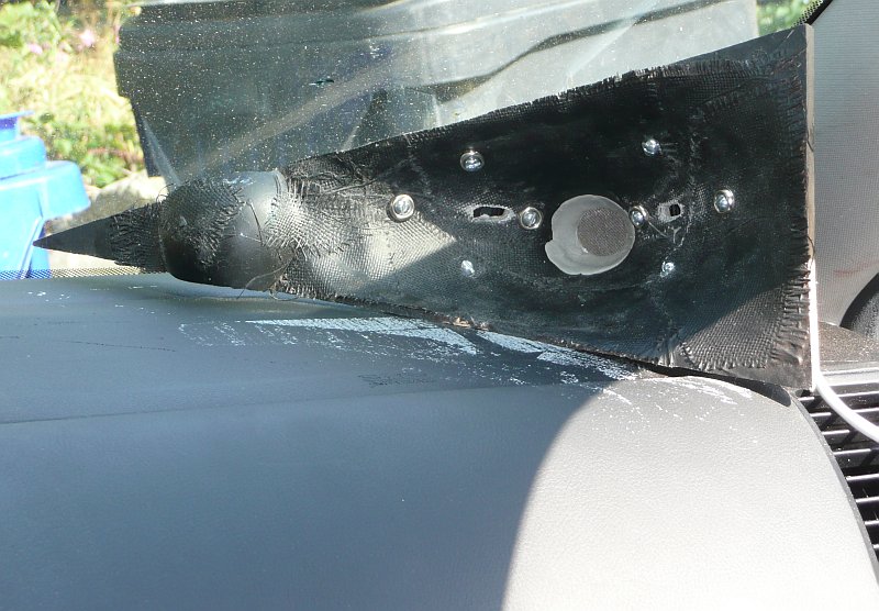
Front view of USD waveguide with roundover and reticulated foam insert
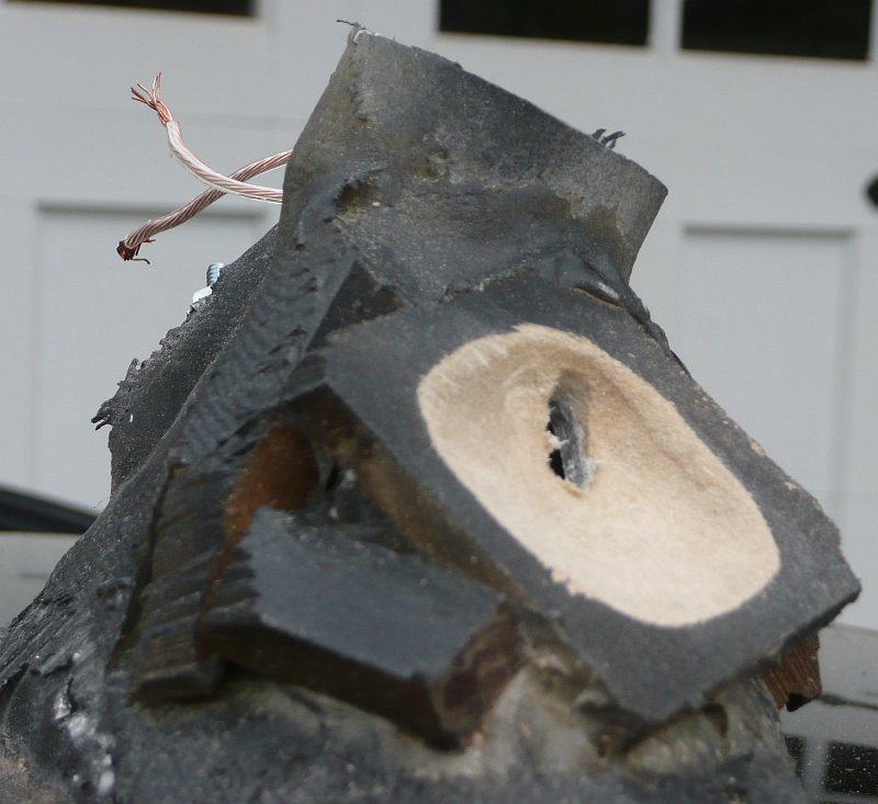
Overhead view. Roundover consists of 2" PVC pipe. I tried a "half roundover" and a full roundover. The full roundover was a bit more effective than the half roundover. This waveguide really sees a big improvement with the roundover.
My theory is that physically pressing against the horn made it more rigid.
So I spent the whole weekend going crazy with cross braces, constrained layer damping, and even braces right THROUGH the horn.
The measurements confirm my suspicions; both the peak and the dip are significantly reduced.
Even better, the roundover on the horn improved the directivity. This means that a bit of EQ will smooth out the response on AND off axis.
(EQ is most effective when the directivity is constant; otherwise the speaker is only flat on ONE axis, and the reflected energy isn't consistent with what you hear on-axis. Basically the speaker sounds odd if this pre-req isn't met, and it won't image.)
Anyways, here's some pics of the new and improved horns. I've also included pics of the USD waveguides, for comparisons sake. The USD waveguides have a roundover at the moment too. I measured them and found the roundover made a huge improvement.
I will post measurements of the improved horn, along with measurements of the USD waveguide, shortly.
Note there's a brace right THROUGH the horn now, I've added a layer of glass with a sandwich of clay and liquid nails in the center, and there's a roundover now.
It's not pretty, but it's going to be wrapped in grill cloth when I'm finished. All of this will be under the dash. The roundover and the braces helped a LOT.
Side view of USD waveguide
Front view of USD waveguide with roundover and reticulated foam insert
Overhead view. Roundover consists of 2" PVC pipe. I tried a "half roundover" and a full roundover. The full roundover was a bit more effective than the half roundover. This waveguide really sees a big improvement with the roundover.
In my post a few weeks ago, I said that I would post measurements of the USD horns with and without the reticulated foam. The measurements, and a subjective evaluation, are here:
http://www.diyaudio.com/forums/showthread.php?t=151376&goto=newpost
In my post a few weeks ago, I said that I would post measurements of my new midrange horns. Here's the info.
First, here's a measurement of the midrange horn. This iteration of the midrange horn includes the following enhancements:
- reticulated foam in the horn
- cross braces to reduce radiation from the horn
- i replaced the Misco KC5NFD woofer with a Misco JC5RTF-B. This appears to be the same woofer used in the SPL and Lambda Unity horns. I switched woofers because it has a lower FS and seemed to measure a bit smoother.
- I chopped up a piece of 2" pvc and used it as a roundover to reduce diffraction and improve the off-axis response. For more details on this mod, check out the post I made five minutes ago.
The midrange horn, with every tweak I could throw at it
the midrange horn, after I applied some EQ to smooth it out. I didn't EQ it to be flat; I EQ'd to be (fairly) smooth. Once the treble horns are finished I'll use them to provide output from 2khz and up.
The same horn as above, but without the cross braces, and without the roundover.
In the measurements above, you can see that the response of the midrange horns is anything but flat. Believe it or not, they sound quite good. Radiation from the horn is a huge problem with this design, probably because it plays so low. With an F3 of 300hz, and an efficiency in the 90s, this thing can kick out the jams.
Even with constrained layer damping AND braces, it's still vibrating quite a bit. I may add some lead and additional braces, to mellow this thing out.
I have also begun the construction of the hi-frequency horns. They're coming along VERY well. Stay tuned for info on their construction.
Sweet
Nice pics progression and better holes on the interface plate. No chainsaw this time! LOL
Mark
Nice pics progression and better holes on the interface plate. No chainsaw this time! LOL
Mark
All I can say is that you must be out of work as that is a sh1t load of work for someone employed.
All I can say is that you must be out of work as that is a sh1t load of work for someone employed.
I'm getting pretty fast at this now - I can do a full set of 12 polar measurements in about fifteen minutes. If I bought additional microphones, it would go even faster. I built a jig that has PVC pipe "slots" for the mic, so you just drop the mic into position, and hit "record."
The midrange horns aren't perfect, they still need additional cross braces to keep them from resonating. But they're good enough for now. So it's time to build the high frequency horns.
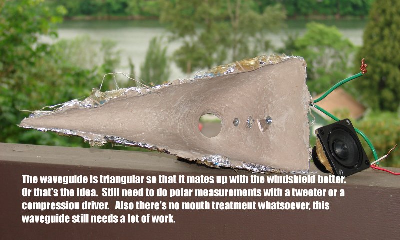
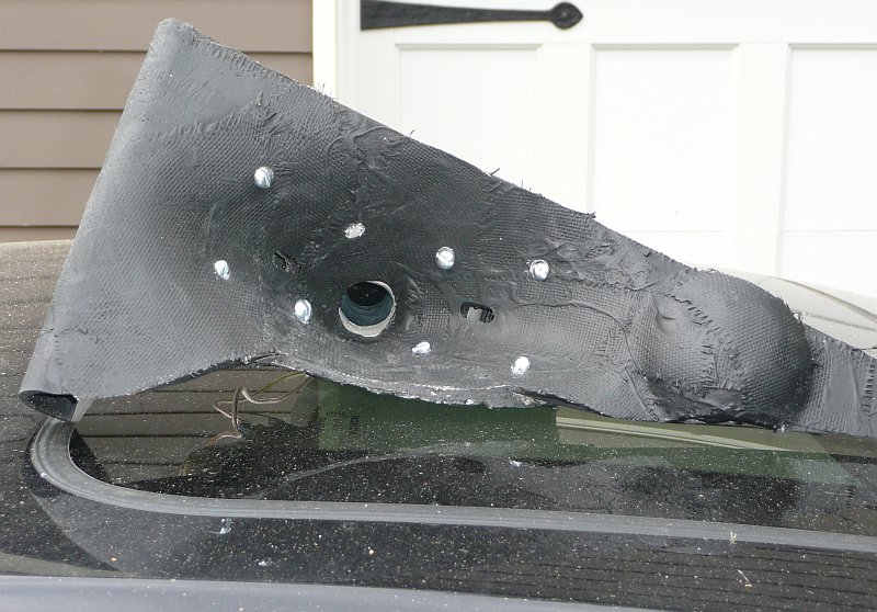
The high frequency waveguides use a triangular baffle so that they'll fit into the corners of the dash. Last summer I built a waveguide with a triangular mouth, and that didn't work out so well. Based on what I've learned, it's important to maintain a circular or elliptical mouth for as long as possible. The waveguide with a triangular mouth didn't measure well.
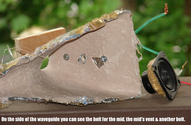
The triangular waveguide from 2008. Don't do this - it doesn't work.
And another pic...
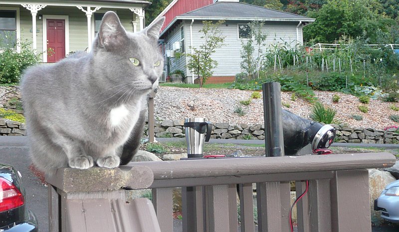
I've built a bunch of unity horns, and I've noticed that mounting the woofers on the wall of the waveguide works surprisingly well. I decided to take a chance, and mounted the compression driver on the wall of the waveguide. This is unorthodox, but it has two big advantages here. First, it allows me to angle the waveguide up by 30 degrees or so. The car's instrument cluster takes up a lot of space, so firing OVER the instrument cluster is A Good Thing. Second, mounting the compression driver on the wall of the waveguide allows me to push it back an extra inch. In the side view you can see the waveguide would simply take up more space if it was firing straight.
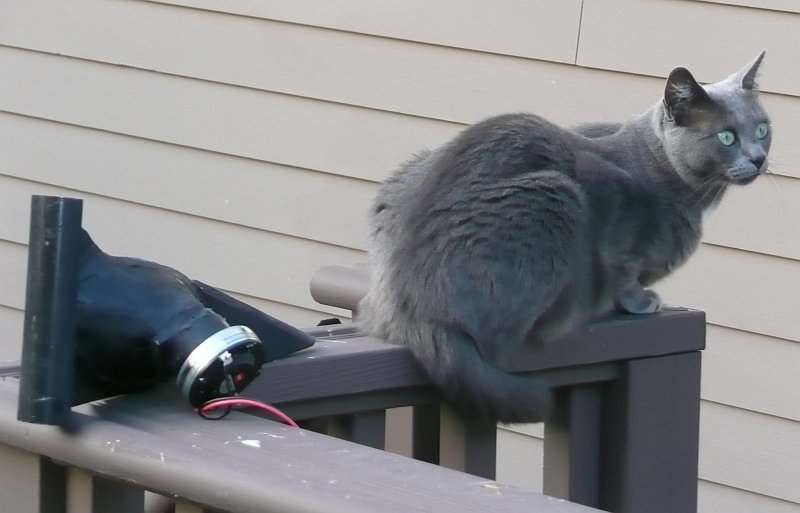
That's not my cat. But she does a good job of demonstrating the scale of this waveguide!

I put a lot of effort into making a non-resonant baffle with a serious roundover. That's a two-inch roundover on the left.
From the side, you can see that the vertical coverage angle blends smoothly into the curve of the windshield. The horizontal coverage angle doesn't blend as smoothly, which is why I have a big roundover on the left. On the right is a semi-sphere which is placed there to "break up" diffraction in the corner.
When I put a Unity in my car three years ago, my girlfriend said that "it looks like there's a bomb on the dash." This waveguide is half the size, and I think the baffle helps it blend in. It's not pefect, but I can live with it. From the passenger side it's barely visible over the instrument cluster.
Here's the Unity horn from 2006. Note that:
The new waveguide actually uses the exact same mold as the waveguide from 2006. If you look closely at the throat you can see I cut it at a 36 degree angle to mount the waveguide to the wall, then used clay to mate it perfectly to the throat.
The high frequency waveguides use a triangular baffle so that they'll fit into the corners of the dash. Last summer I built a waveguide with a triangular mouth, and that didn't work out so well. Based on what I've learned, it's important to maintain a circular or elliptical mouth for as long as possible. The waveguide with a triangular mouth didn't measure well.
The triangular waveguide from 2008. Don't do this - it doesn't work.
And another pic...
I've built a bunch of unity horns, and I've noticed that mounting the woofers on the wall of the waveguide works surprisingly well. I decided to take a chance, and mounted the compression driver on the wall of the waveguide. This is unorthodox, but it has two big advantages here. First, it allows me to angle the waveguide up by 30 degrees or so. The car's instrument cluster takes up a lot of space, so firing OVER the instrument cluster is A Good Thing. Second, mounting the compression driver on the wall of the waveguide allows me to push it back an extra inch. In the side view you can see the waveguide would simply take up more space if it was firing straight.
That's not my cat. But she does a good job of demonstrating the scale of this waveguide!
I put a lot of effort into making a non-resonant baffle with a serious roundover. That's a two-inch roundover on the left.
From the side, you can see that the vertical coverage angle blends smoothly into the curve of the windshield. The horizontal coverage angle doesn't blend as smoothly, which is why I have a big roundover on the left. On the right is a semi-sphere which is placed there to "break up" diffraction in the corner.
When I put a Unity in my car three years ago, my girlfriend said that "it looks like there's a bomb on the dash." This waveguide is half the size, and I think the baffle helps it blend in. It's not pefect, but I can live with it. From the passenger side it's barely visible over the instrument cluster.
Here's the Unity horn from 2006. Note that:
- it looks like a bomb
- There's no baffle or mouth treatment whatsoever
- ten cents worth of black paint sure helps the new one blend in
The new waveguide actually uses the exact same mold as the waveguide from 2006. If you look closely at the throat you can see I cut it at a 36 degree angle to mount the waveguide to the wall, then used clay to mate it perfectly to the throat.
Just ordered one of those flat-diaphragm tangband woofers
An externally hosted image should be here but it was not working when we last tested it.
On the waveguide thread Dr Geddes mentioned a flat diaphragm is a good match for an OS waveguide. I don't know when I'll get a chance to build anything for it, but I'm willing to add it to the collection. Maybe I'll slap it on a unity horn and see how well it works 🙂
http://www.tb-speaker.com/detail/1230_04/w4-1805s.htm
Last edited:
On the waveguide thread Dr Geddes mentioned a flat diaphragm is a good match for an OS waveguide.
That's true only if the throat is the same area and shape as the diaphragm. Some people misunderstood this. For a 4" diaphragm that's going to be a pretty big waveguide. At 4" it won't work very well above about 2 kHz and for a reasonably useful bandwidth of say a decade that's a waveguide down to about 200 Hz. Thats a huge mouth to get any kind of control. So that driver would be ideal for a waveguide that was about six feet across and probably four to six feet long, not ridiculous, but not practical either.
On Thursday I put together a basic crossover for the woofer and the treble horns, and dialed in a bit of EQ. The treble horns make a great improvement in the system. Up until this point I've been using EQ to push the midrange horns all the way up to 10khz. Because the horns are covering such a wide bandwidth, it sounded like they were struggling, particularly at high volumes. While the woofers can take the power, the fiberglass horns would start to buzz. Adding the high frequency horns removed most of the harshness. The BMS compression drivers have an efficiency that's close to 110db. Even a single watt is more power than you need with the BMS.
Thanks to this, the addition of the BMS compression drivers makes the system sound "effortless."
On the downside, the BMS waveguides bring the soundstage forward a few inches. The midrange horns are buried deep under the dash, while the BMS waveguides are a few inches closer.
Adding reticulated foam to the BMS waveguide makes the soundstage go back a few inches. I believe it does this by reducing diffraction near the mouth and the windshield. The foam is essential.
Also, the soundstage is at eye level once the BMS waveguides are turned on. This is because of the Haas effect, as well as high frequency psychacoustic cues.
Here's some more data on the treble waveguides. For background on these, see this post:
http://www.diyaudio.com/forums/showpost.php?p=1921456&postcount=29
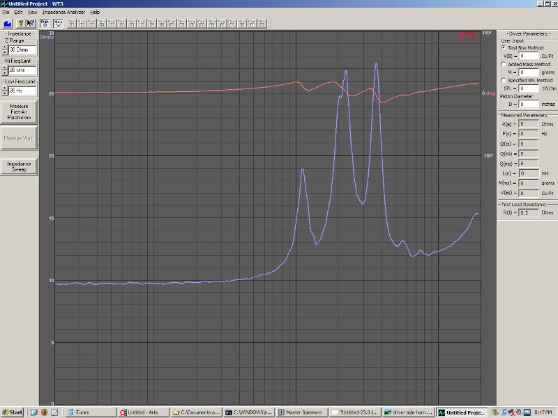
This is the measured impedance of the BMS 4540ND-16 on my waveguides. You can see that the impedance is very peaky, which is normal for a compression driver. Unfortunately, these peaks make it very difficult to make a passive crossover for a compression driver.
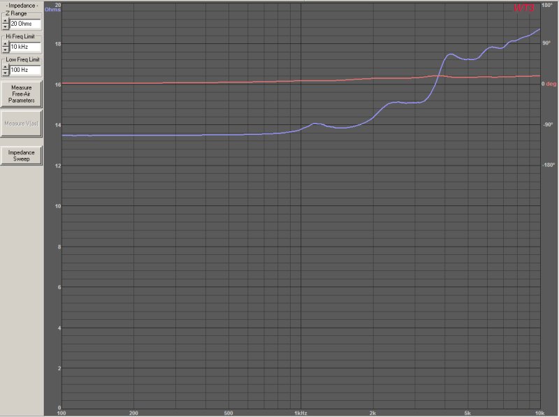
This is the measured impedance of the BMS 4540ND-16 on my waveguide, but with an L-pad. Basically an L-Pad is two resistors used to "pad" down the compression driver so that it matches the midranges. A side benefit of the L-pad is that it smooths out the impedance curve, and makes it easier to cross over.
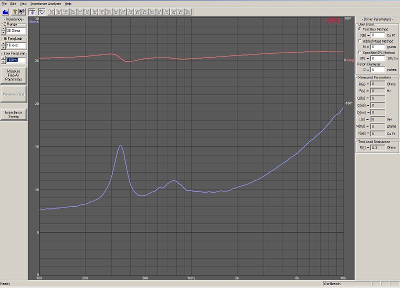
This is the measured impedance of the Misco JC5RTF midranges, on my horns. There's a double peak in the impedance because of the horn.
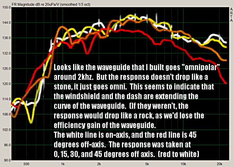
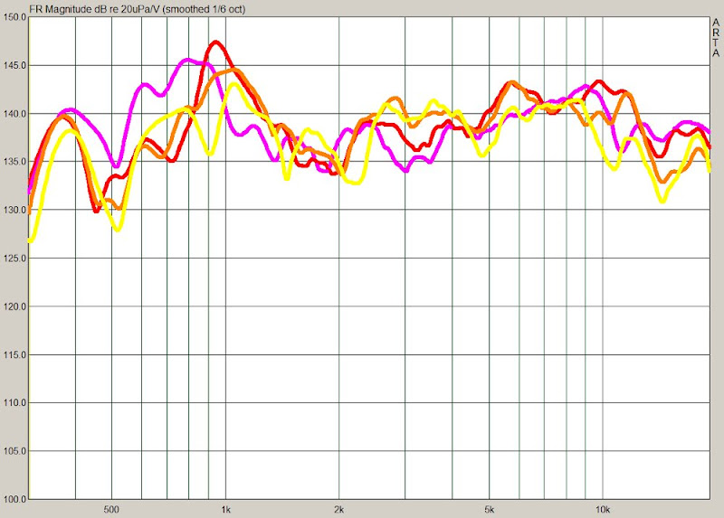
Here's the SPL response of the BMS compression driver, with no crossover, on the waveguide and in my car. This is pretty darn good I'd say. In my opinion, the oblate spheroidal curve, the baffle, and the roundover is contributing to the relatively smooth response.
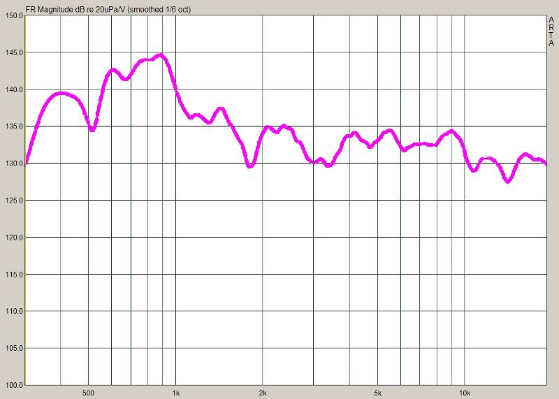
Here's the SPL response of my oblate spheroidal waveguide from 2006, in the car. The response is more ragged. IMHO, it's due to the lack of a baffle or a roundover. It's still quite good though.
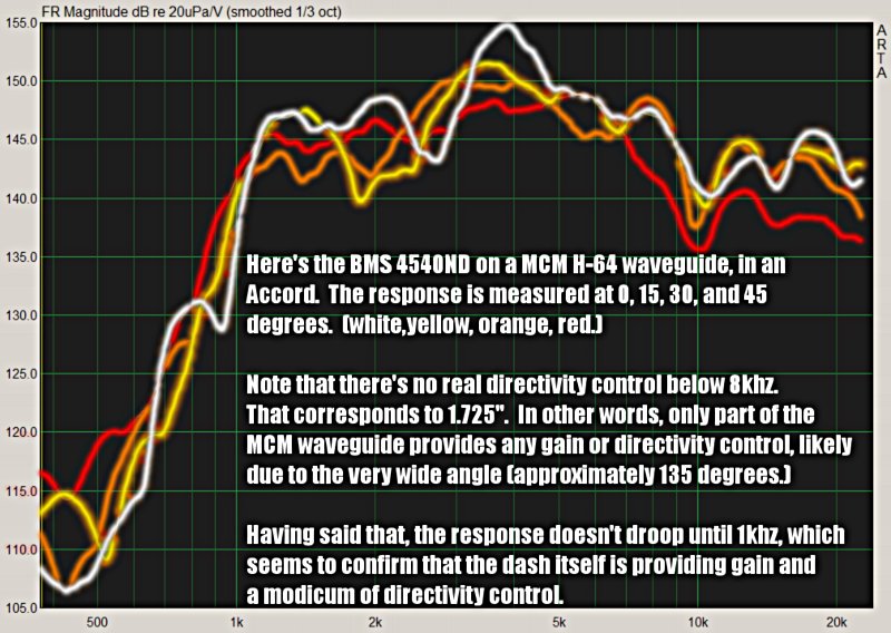
For the sake of comparison, here's the SPL response of the MCM waveguide that's been getting a lot of attention lately. This is the one used by Zaph in his waveguide project. As you can see in the graphs, it's response and it's directivity is nowhere near as good as an OS waveguide.
Here's the response of my woofers *and* my tweeters, with a very basic crossover.
Here's the response of my woofers *and* my tweeters, with a the crossover above, and a bit of EQ.
For comparison's sake, here's the measured response of a set of USD waveguides, with and without the tweaks I mentioned on the last page. You can see that my setup has the following improvements over the USD setup:
- My setup plays higher, and lower.
- My waveguides on the dash have higher efficiency that the USD.
- Above 2khz, the treated USD horns have better directivity than mine do. I believe this is because the USD horns use a diffraction slot, and mine do not. After treatment, the USD horns perform *very* well above 2khz. Unfortunately, I don't like my soundstage around my kneecaps.
- The USD horns and my waveguides suffer from a dip around 1800hz, which may be due to the car itself. It is less severe in my setup than in theirs. The treated USD horns have a six db dip at 1800hz; my horns have a 3db dip. The on-axis dip in the *untreated* USD horns is over TEN db!
I'd say results are very promising.
Regarding dampening of waveguide material I'd go for applying something like couple of milimeters thick, elastic but basically inert material, and then coat it with thin layer of definitely harder material. This could further dampen these resonanses and still provide hard surface needed for clarity.
This may sound a bit weird, but I got over something like this when I painted plasticine with fast drying paint. You could even make small cavities before painting to achieve golf ball pattern used on some high-end speaker membranes - why not to try it on internal surface of the horn.
Wel, that's just a thought. Use it or abuse it, and good luck with your Pacific Northwest meeting! 🙂
In a post a few days back, I demonstrated that I'd improved the frequency response of my midrange horns by integrating a substantial roundover under the horn, bracing it, and deadening it. More information can be found here:
http://www.diyaudio.com/forums/showpost.php?p=1920171&postcount=25
There's a couple problems with the mids. First, the compression driver has a sensitivity of around 110db, and vanishingly low distortion, so the mids have a lot to live up to. Second, there's a dip around 500hz.
Based on that, I decided to turn the waveguides on the dash into a Unity. This is very similar to the project I did a few months back. I killed that project, for this one, because the waveguides were becoming unwieldy and overly complex.
Of course, a Unity on the dash and horns *under* the dash is anything but simple...
But what can I say? Putting midranges on the waveguides is the simplest way to smooth the response, and increase the efficiency. It's a win-win.
Without further ado, here are some pics.
The slots to the left and the right are for The Unity midranges. The grey stuff near the throat is clay insulation.
The left waveguide, which is basically finished, and the right waveguide, which I've barely started on.
Left waveguide, after I sanded and filed it down like crazy, to reduce diffraction.
The new waveguide, with just a basic baffle and a single layer of glass
The new waveguide, in desperate need of sanding and filing
Two horns and two waveguides. Three of them are basically finished.
Last edited:
The midrange horn and high frequency waveguide, all but finished. Note the two entry holes for the Unity midranges.
I think the black paint does a world of good
If you look closely, you can see the TangBand W2-852SH woofers through the holes.
Ubiquitous side view
The mounting plates for the midranges are dished out like an ice cream scoop. By reducing the depth of the holes we raised the upper limit of the midranges. A bigger hole would do this too, but a bigger hole screws up the response of the tweeter. So we want to use the shallowest holes we can. Dishing out the plate accomplishes that. See the Synergy Horn patent for more info.
More detail of the mounting plate
You can see from the side view that I really filed and sanded the waveguides extensively, so diffraction is reduced. The termination of the wavguide is gentle and gradual.
Here's the waveguide on the dash. From the side, you can see that the vertical angle is almost a perfect match for the dash. It's difficult to see in the pic, but it's an excellent match for the windshield as well. There's a gap to the left and the right, which is why the baffle will have a diffraction treatment.
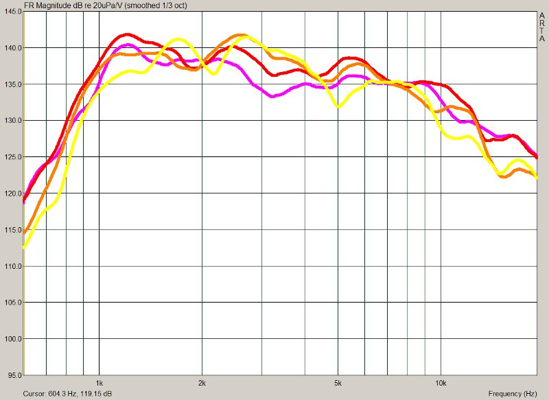
In this project, I discovered that an elliptical oblate spheroidal waveguide, coupled to a compression driver, yielded smooth and controlled response in the car. Here's a graph of the compression driver on the waveguide to demonstrate this. This is a polar measurement in-car, take at 0, 15, 30 and 45 degrees.
The picture below demonstrates the response of the horns under the dash. The efficiency is fairly good, but there's a resonance at 500hz which is affecting our polar response. And we also have more output than we really need above 1500hz.
Ideally, we'd like to see the response above 1500hz fall off like a cliff, because a steep rolloff will reduce distortion, improving clariy of the entire system.
In order to bring the soundstage up, increase the efficiency, and smooth the response, I turned the waveguides on the dash into a Unity horn. As a Unity horn, the midrange output is now emanating from waveguides on the dash AND horns underneath.
This pic shows what the Unity waveguides look like, up close.
Here's the response when all SIX midranges are playing. There are two mids in the Unity waveguide, and one underneath the dash, in a horn.
This is an early example of what the front stage measures like. This measurement includes the compression driver, the waveguides on the dash, and the horns underneath.
In the pic we can see that directivity is fairly well controlled from 3khz to 20khz, but begins to wander a bit below that.
This is due to the dimensions of the car.
Can someone decode this graph for me?
I'm not looking to be spoon fed or argumentative but everytime I like at these (Patrick's) plots I come to a drastically different conclusion. I see the same horrible polar response that I normally find in cars using direct radiators...
This quote in particular is trouiblesome
I'm not looking to be spoon fed or argumentative but everytime I like at these (Patrick's) plots I come to a drastically different conclusion. I see the same horrible polar response that I normally find in cars using direct radiators...
This quote in particular is trouiblesome
. For that statement to be true I would expect to see lines that are roughly parallel from 3k to 20k (ideally). These things cross multiple times. What am I missing?directivity is fairly well controlled from 3khz to 20khz
Can someone decode this graph for me?
I'm not looking to be spoon fed or argumentative but everytime I like at these (Patrick's) plots I come to a drastically different conclusion. I see the same horrible polar response that I normally find in cars using direct radiators...
This quote in particular is trouiblesome . For that statement to be true I would expect to see lines that are roughly parallel from 3k to 20k (ideally). These things cross multiple times. What am I missing?
To get a clean measurement of a waveguide down to 250hz, you need to eliminate any reflections within 22 feet of the waveguide.*
How do you do that in the car?
The alternative is to measure the waveguide outside of the car. But then you're factoring out the effects of the car, and those effects are important.
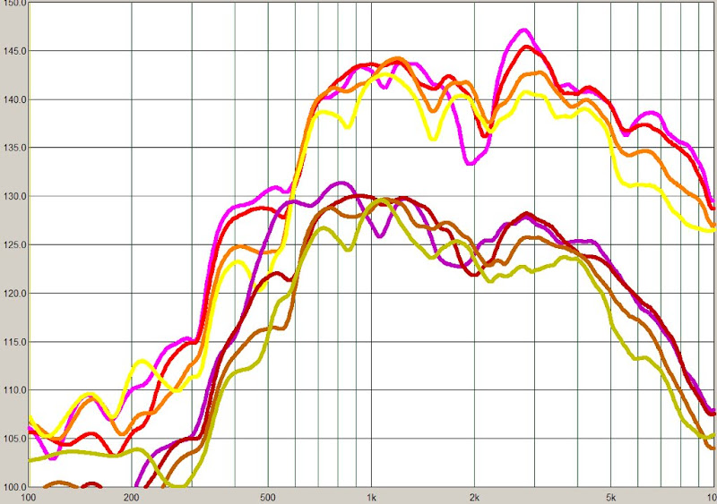
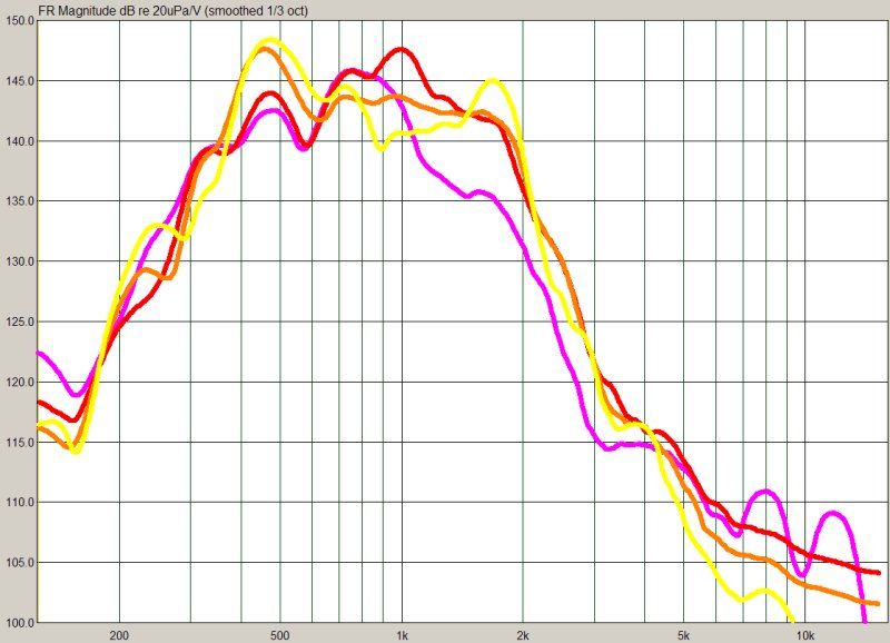
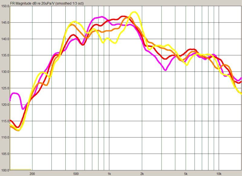
Given this difficult environment, it's no wonder I've never seen anyone else do polar measurements in a car. Some might think I'm wasting my time, and that's fair. Take a look at these two graphs below, and tell me that one isn't better than the other.**
It's all relative.
* A 250hz wavelength is 54 inches long. To get a halfway decent measurement, you should do a gated measurement which captures at least five cycles. That works out to 270 inches, or about 22 feet.
For additional information on measuring horns, look up some posts from Danley. He measures his horns from ten meters away.
** Both graphs are polar measurements in my car. One uses an unbaffled MCM waveguide. The other uses an elliptical oblate spheroidal waveguide on a proper baffle. The response of the second graph is more consistent at all angles, which is what I'm after. The first graph suffers from dramatic peaks and dips as you move from one side to the other. Both waveguides were loaded with the same compression driver, a BMS 4540ND.
Last edited:
Patrick,
Thanks for the reply.
I understand the harsh nature of an automotive acoustical environment. Further I believe that waveguides can offer some assistance in taming that environment. I guess what I was struggling with was the subjective term of "good" directivity control. While it seems to be improved (compared to the first measurements) I would not have considered the results "good" (could be inexperience on my part).
One question about the two sets of measurements. Were they taken with the drivers mounted in the same locations? I typically assume that the environment in an automobile dominates all other acoustic factors. If the drivers were not mounted in the same physical location I would not be sure that the changes in response were provided by the horn/waveguide rather than the environment.
Again thanks for taking the time to explain your thoughts/measurements. I plan on using waveguides in an upcoming installation. I will be sure and post the reulting measurements (likely on DIYMA).
Charles
- Status
- Not open for further replies.
- Home
- Loudspeakers
- Multi-Way
- Creating a Soundstage with Waveguides and Psychoacoustics