Yes, I did build the sub but I think it was in 2003. In regards to the horn, I heard it after the show at the guy's house that bought it. It's the best of the 'fullrange driver in a front horn' genre that I've heard. The other one that I've heard several times was the 150Hz Oris horn which was a tractrix flair. It always had this weird, shut in sound that I immediately recognized upon listening to my own material on it - the best way I know to describe it. After about 10 minutes I'd get used to the sound and not notice it. The system you posted the pic of sounded much more neutral and had pretty flat response when I measured it (I remember being surprised). I wish I'd taken off axis measurements as well, but I didn't think to do that back then.
For example, your speakers are probably the best example (the biggest baffle outside the horn), but even there the cabinet is basically the size of the horn with the radius plus the radius at the edge of the cabinet. So if you have a horn with a full roll back, it will be almost identical to this.
"Almost" is a pretty big fudge word, but in my opinion there is a significant difference. First the sides of my cabinet don't roll-around, i.e. they drop back at 90° not 180° - which is significant in diffraction reduction, and there is substantial baffle in the corners - less so at the edges. You only referenced the edges somehow missing the larger portions in the corners. You wouldn't have a bias for the Le'Clerq horn would you?
Last edited:
I wish I'd taken off axis measurements as well, but I didn't think to do that back then.
Back then? Who does it now? It's still seldom seen. I wonder why that is?

No, I specifically did mention the corners, although I guessed you missed my reference. No big deal. Yes, you can argue about the magnitude (or one could simulate it and show it or build the different varieties and measure if so inclined), but it's all a continuum and yours would fall between an infinite baffle and a round horn with a full roll back, but I'm saying they're closer to the full roll back than they are to an IB.
My polar measurement reference was to myself - I do it now. However, I know that Harman also does it in developing all their speakers even if they don't show the results.
My polar measurement reference was to myself - I do it now. However, I know that Harman also does it in developing all their speakers even if they don't show the results.
No, I specifically did mention the corners, although I guessed you missed my reference.
I hate to quibble, but this statement is incorrect. I reread the post and you did not mention the corners, only the edges.
"the cabinet is basically the size of the horn with the radius plus the radius at the edge of the cabinet"
Sure it's all a continuum - but I'd rather be closer to the infinite baffle than the other way.
John
Are you repainting the Summas?
Those are my speakers, I'm surprised you don't recognize the finish. Patrick seems to use my pictures of assembly a lot, I'm guessing because they show the speaker taken apart. I probably will finish mine at some point, but after redoing the center with the paint you recommended, it came out with a similar hardness and finish to the original acrylic satin black finish I had done. The problem with that finish turned out to be curing time. It took a few weeks before they were fully cured.
What do they call it in microwaves, a corrugated horn, Chaparral feed??
Could one surround an acoustic baffle with 1/4 wave slot that bucks the
step... Or maybe covered with some sort of passive radiator, if ordinary
slot around the baffle is not practical to tune that low??? Could such a
slot make the baffle appear larger?
Sorry, this idea is very half baked... I know that pressure waves do not
behave quite the same as electromagnetic waves, and a loudspeaker is
not necessarily an acoustic antenna....
Modes in a waveguide can't be the same when there is no 90deg relation
between E and H fields... There is just pressure and inertia and heat...
I don't know that such a circumferential slot as I propose is relevant to
the way audio propagates around the face of an acoustic enclosure?
http://www.chaparral.net/products/feedhorns/super.html
Last edited:
What do they call it in microwaves, a corrugated horn, Chaparral feed??
Could one surround an acoustic baffle with 1/4 wave slot that bucks the
step... Or maybe covered with some sort of passive radiator, if ordinary
slot around the baffle is not practical to tune that low??? Could such a
slot make the baffle appear larger?
Sorry, this idea is very half baked... I know that pressure waves do not
behave quite the same as electromagnetic waves, and a loudspeaker is
not necessarily an acoustic antenna....
Modes in a waveguide can't be the same when there is no 90deg relation
between E and H fields... There is just pressure and inertia and heat...
I don't know that such a circumferential slot as I propose is relevant to
the way audio propagates around the face of an acoustic enclosure?
http://www.chaparral.net/products/feedhorns/super.html
Those kinds of feedhorns work on very narrow bandwidths and the kind of thing you are talking about is feasible. But with acoustic waveguides the wavelengths vary over a factor of about 10 or more. They are anything but narrow band.
I hate to quibble, but this statement is incorrect. I reread the post and you did not mention the corners, only the edges.
No, you love to quibble which, I assume, is why you post here so much (apart from the free advertising). Of course I'm here too, so...
Fine, I concede that I did not specifically mention the area of the corners, but I did mention the corners in the last sentence of that paragraph when I said the varying distance from the edge of the round waveguide they provide could smooth out the effects of diffraction. However I still find it laughable that you are so hung up on this small area in comparison to an IB, as your baffle area is basically the minimum possible to hold your components (horn and woofer) and have the edge radius when using flat panels for your cabinet.
I'm not "hung up" on anything. You post incorrect statements and I correct them. Then you get defensive.However I still find it laughable that you are so hung up on this small area in comparison to an IB ...
No, you love to quibble which, I assume, is why you post here so much (apart from the free advertising). Of course I'm here too, so...
Fine, I concede that I did not specifically mention the area of the corners, but I did mention the corners in the last sentence of that paragraph when I said the varying distance from the edge of the round waveguide they provide could smooth out the effects of diffraction. However I still find it laughable that you are so hung up on this small area in comparison to an IB, as your baffle area is basically the minimum possible to hold your components (horn and woofer) and have the edge radius when using flat panels for your cabinet.
Everyone else gets your statement IN FULL CONTEXT (..and of course "edges" include "corners"):
"..your speakers are probably the best example (the biggest baffle outside the horn), but even there the cabinet is basically the size of the horn with the radius plus the radius at the edge of the cabinet. So if you have a horn with a full roll back, it will be almost identical to this. I suppose you could argue that a round horn in a square cabinet with large radii would be better as it would distribute the diffraction somewhat due to varying distances from the edge of the horn to the (square) edge of the cabinet."
"..it's all a continuum and yours would fall between an infinite baffle and a round horn with a full roll back, but I'm saying they're closer to the full roll back than they are to an IB."
"..but I'm saying they're closer to the full roll back than they are to an IB."
For Earl it's easier to "quibble" with portions of your statement than address the full statement in context with anything other than a:
"..Sure it's all a continuum - but I'd rather be closer to the infinite baffle than the other way."
..because to do so would present his speakers in a "negative light" based on his own requirements. (..frankly "requirements" that he makes to much of IMO.) It's marketing evasion with an emphasis to discredit alternative designs that others may perceive as comparable.
BTW, the implied premise that a "box" is better than a full round over with respect to diffraction is also pure marketing cr@p. Or half-truth
 .
.The relative angle and the amount of pressure on that angle is the key to the negative association with diffraction. A full round-over with a gradual angle is far more likely to have *less* diffraction that we deem as harmful to sound reproduction.
And John,
I kind'a feel sorry for Earl.
If he had bothered to do any research on you, your capability, and your propensities, he would have realized how colossally stupid it was/is to "quibble" with you. He should have just not responded. As it is now, I think its more than likely you'll make a full study of this that will be far less refutable, with a conclusion far less supportive of Earl's products. Eh, sometimes free marketing can "bite you on the @ss".
This is a bit off topic, but people have emailed me about unity horns, since I've spent a few years experimenting with them.
Here are the questions I am often asked, along with the answers.
How big should the holes be in a Unity horn?
If I were you, I wouldn't use holes. The design of the ducts on the Synergy horn and the Yorkville Unity horn is superior. This makes a BIG and measurable difference on the performance. If you *must* use a hole, put it at a location that's 1/4 wavelength from the upper limit of the midrange. So if you want to run the midrange to 2000hz, put the center of the hole 1.6875 inches from the throat. (13500 inches per second / 2000hz / 4)
What can I do to improve the Unity horn?
OK, OK, I made up the last one. Nobody ever asks me how to improve the Unity horn. But anyways, here are a few ideas:
- Put a big fat roundover on the mouth of the horn. My reference speakers are a set of Gedlee Summas, and they image very well. I think that part of the magic is the roundover on the cabinet, and the waveguide. If I were going to change ONE thing about the Unity horn, it would be the mouth termination. An unterminated horn will never image as well as a properly terminated horn.
- You don't have to use a square conical horn with a Unity. Consider using a waveguide. The main advantage of a square conical horn is that the Unity can be arrayed, and the wooden horn is durable and easy to build. In a prosound environment, these are good things, but at home, a real waveguide offers a few advantages too.
Hope that helps...
Thanks for the input on the unity horns. I will probably never build a pair, but the topic is of great interest anyway! A couple of questions to the points mentioned above:
I think I have read in one of Tom Danleys posts somewhere that there is an advantage to put the holes/ducts in the corners of the horn. If this is correct it makes your suggestion of using a waveguide less atractive. By waveguide, did you mean round conic horn, or did you also have Earls waveguide throat (don't know what else to call it) in mind?
Do you think the transition from the 60 degrees to 90 degrees has any bad impact on sound, like diffraction? Would it be better if space is not an limitation to build the horn so big that one can avoid the narrowing pattern and have just one hornflare with the additional roundover?
Thanks for your comments. Hope my questions make sense.
Thanks for the input on the unity horns. I will probably never build a pair, but the topic is of great interest anyway! A couple of questions to the points mentioned above:
I think I have read in one of Tom Danleys posts somewhere that there is an advantage to put the holes/ducts in the corners of the horn. If this is correct it makes your suggestion of using a waveguide less atractive. By waveguide, did you mean round conic horn, or did you also have Earls waveguide throat (don't know what else to call it) in mind?
The advantage of putting the midrange holes in the corner of the horn is that the horn walls extend the curve of the midrange holes. That reduces turbulence, which allows you to use smaller holes for the same level of SPL. The use of smaller holes improves the frequency response of the compression driver.
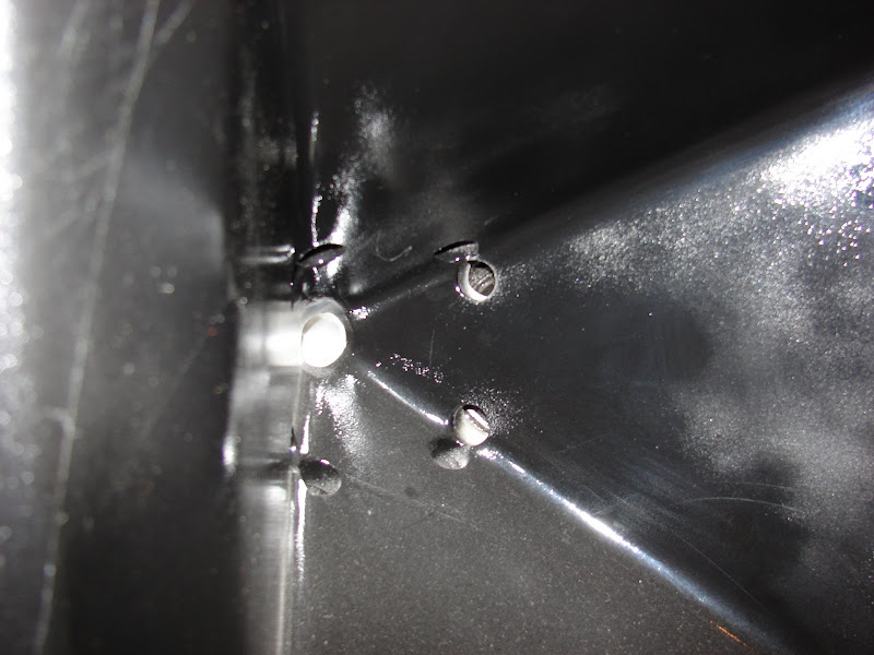
Here's a pic.
I wouldn't even use holes, I'd use a slot, like the Yorkville Unity. Or a frustrum, like the Synergy horns.
IMHO, reducing turbulence in the ports isn't a huge issue at home. At the tuning frequency of the bandpass midranges, two midrange holes with a diameter of 12mm is equivalent to a bandpass subwoofer using dual 102mm ports.
Do you think the transition from the 60 degrees to 90 degrees has any bad impact on sound, like diffraction? Would it be better if space is not an limitation to build the horn so big that one can avoid the narrowing pattern and have just one hornflare with the additional roundover?
Thanks for your comments. Hope my questions make sense.
The "real" Unity horn transitions from sixty degrees to ninety degrees at the mouth. This is a clever way to smooth the horn's response, as a bigger mouth has smoother response (but a higher F3.)
Is the transition from 60 to 90 degrees bad? Well think about this:
What would sound better. A transition from 60 to 360 degrees, or a transition from 60 to 90 to 360 degrees?
I'll take the former, or better yet, a transition that goes 60 degrees, 61 degrees, 62 degrees, ...
A roundover improves polar response, but a roundover isn't practical for the "real" Unity horn, since it's designed to be arrayed. I *do* think a roundover is downright essential for home speakers.
The compression driver isn't bothered/overloaded (as a microphone) by sharing the
most heavily pressurized end of the same waveguide with all those midrange drivers?
If I put my hand on a tweeter cone and press it beyond xmax, isn't this the same
thing, only intermodulated by midrange frequencies..?
I'm sure there is plenty of evidence this doesn't happen. I'm just not sure why?
most heavily pressurized end of the same waveguide with all those midrange drivers?
If I put my hand on a tweeter cone and press it beyond xmax, isn't this the same
thing, only intermodulated by midrange frequencies..?
I'm sure there is plenty of evidence this doesn't happen. I'm just not sure why?
Last edited:
Post 49, picture 2, shows an unterminated unity horn sittin on a box.
Now, there's a lot of unused volume behind that unity. If we enclose
it, but leave a gap around the front edge. And then cover that gap
with a half roll surround. Can we then tune it (with sandbags inside
or whatever) to suck out the baffle step frequency? Chaparral Style?
Then this suckout hopefully cancels the wave as it tries to turn the
corner?
I think then, at the step frequency, we are only driving a small enclosed
volume behind the horn, and not the entire half space behind the horn???
But maybe this is not sensible math, only imagination getting the best
of me...
Hopefully the roll covering the slot would not make edge diffraction any
worse than it already is over the higher frequencies...
Is the baffle step and the cutoff of the horn mouth the same thing, or
two different things in the picture referenced above? I am not entirely
clear on those definitions either...
Last edited:
The compression driver isn't bothered/overloaded (as a microphone) by sharing the
most heavily pressurized end of the same waveguide with all those midrange drivers?
I would have to hypothesize and have done so in the past, that there is a lot of interaction between the mids and the compression driver. Not so much resulting in nonlinear distortion, but certainly frequency response aberations. This would be worst case at the crossover. I have long wanted to see detailed results form one of these devices done in a way that I know what to expect. Tom was going to do that for me but never did to my knowledge. His data at 10 m, like all data taken at those distances, always seem to look "too clean". I've seen data from speakers that I know well taken this way and it always looks far better than what I get in my own measurements. Needless to say, I trust mine and question the rest.
Thanks for your reply. By the way, there is a diy unity horn "in the pipeline" by William Cowan at http://cowanaudio.com/.
Post 49, picture 2, shows an unterminated unity horn sittin on a box.
Now, there's a lot of unused volume behind that unity. If we enclose
it, but leave a gap around the front edge. And then cover that gap
with a half roll surround. Can we then tune it (with sandbags inside
or whatever) to suck out the baffle step frequency? Chaparral Style?
Then this suckout hopefully cancels the wave as it tries to turn the
corner?
I think then, at the step frequency, we are only driving a small enclosed
volume behind the horn, and not the entire half space behind the horn???
But maybe this is not sensible math, only imagination getting the best
of me...
Hopefully the roll covering the slot would not make edge diffraction any
worse than it already is over the higher frequencies...
Is the baffle step and the cutoff of the horn mouth the same thing, or
two different things in the picture referenced above? I am not entirely
clear on those definitions either...
Yes, that is exactly what I would recommend. Put the horn in a box, and add a roundover to the enclosure.

In Danley's synergy horn, he's using a much larger mouth for the horn, AND it's fully enclosed. The use of a larger mouth reduces the need for a roundover to some extent, since frequency response aberrations are more audible at higher frequencies than at lower frequencies.
An externally hosted image should be here but it was not working when we last tested it.
For instance, in a Unity horn the mouth is 15" across IIRC. That means that there will significant reflections at the mouth as high as 900hz. (speed of sound / 15")
In a synergy horn the mouth is double the size, so response aberrations due to reflections off the mouth will begin at a much lower frequency.
Of course, ANY discontinuity in the horn will create diffraction, so given a choice of a big mouth with a sharp exit, or a small mouth with a smooth exit, I'll take the latter.
But the latter isn't easily arrayed.
Last edited:
- Status
- This old topic is closed. If you want to reopen this topic, contact a moderator using the "Report Post" button.
- Home
- Loudspeakers
- Multi-Way
- Creating a Soundstage with Waveguides and Psychoacoustics