Does anyone know where the qcc3008 modules can be found? Few sellers I spoke to say there is backlog of the whole range of these chips.
Also, from what I've gathered, this is the tool needed to program CSR8645, QCC300X series:
Bluetooth CSR Burner USB SPI S to 1.8V Download Programming Debugging Development Mass Production Tool|Cable Winder| - AliExpress
correct?
btw for anyone with noise issues on qcc300x modules, if you are using the analog out from SoC directly, try using differential outputs, cause most amp boards couple the neg(-) side.
Also, from what I've gathered, this is the tool needed to program CSR8645, QCC300X series:
Bluetooth CSR Burner USB SPI S to 1.8V Download Programming Debugging Development Mass Production Tool|Cable Winder| - AliExpress
correct?
Yes, that CSR SPI dongle is what you need.
It's really worth the money imho. Sometimes the official vendor tools can save you a lot of hastle. Reminds me of the ADAU1701 and that USBi stuff.
TSW with I²C output running!
Again progress: I was now able to get TWS + I²S running. Background for that requirement is, that I have more than two speakers and would really love to use the internal DSP and crossover of the CSR8675 for both high/mid speakers and one low speaker.
Since the CSR8675 has two differential outputs, I either needed to do crossover work after the fact (either analogue or with a real DSP like ADAU1701) OR I use I²S to get an additional pair of outputs.
I decided for the latter, since it would really save me footprint and effort. An I²S DAC is cheap to have and the implementation and testing is far more straight forward than designing an analogue crossover (which then would have a fixed dropoff frequency) or implementing a custom ADAU1701 solution.
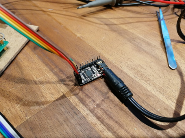
For the testing I now used a PCM5102A on a generic breakout board. Those can be had for pretty cheap. I scored 5pcs for 25€ on amazon.
The PCM5102A is pretty simple. It does not use I²C for configuration, but rather has some Pins that can influence its mode of operation. Rest is determined by the incoming data from I²S.
I went with the following configuration:
FLT -> low
DEMP -> low
XSMT -> high
FMT -> high
This will automatically have the PCM5102A unmuted and waiting for left-aligned data.
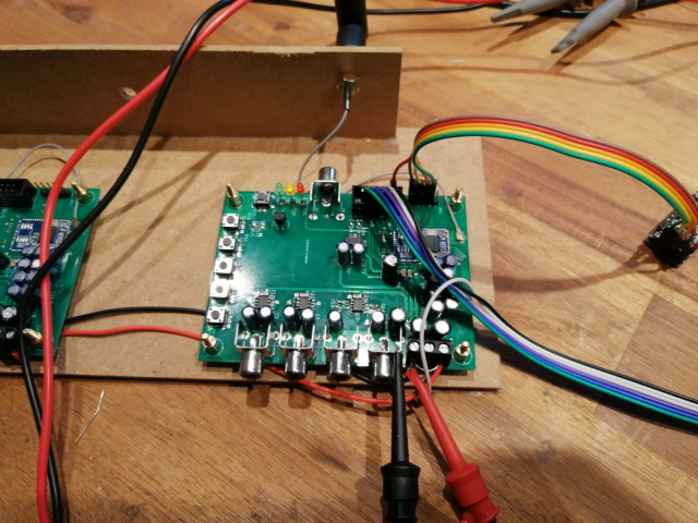
Connection to the CSR8765 is made via dunpont connectors, connecting GND, VCC (3.3V), LRCK/SYNC, DIN and BCK. We don't need SCK for this, so that pin can be left open or tied to ground.
There is some configuration to be done inside the ADK Configuration Tool. I am using Version 4.3.15 with the default sink application.
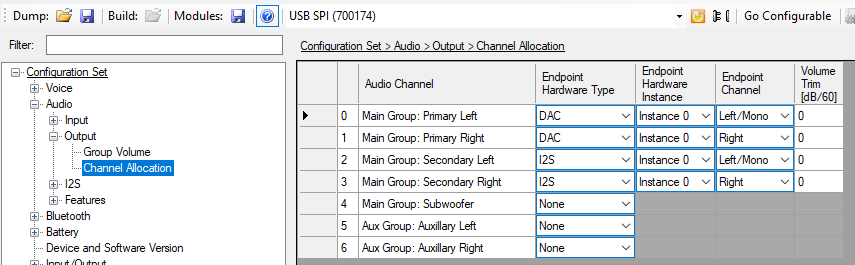
First of all, we need to enable routing of audio to the I²S output channel:
Next is the specific I²S configuration:
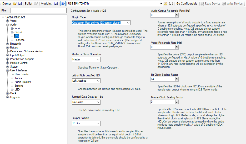
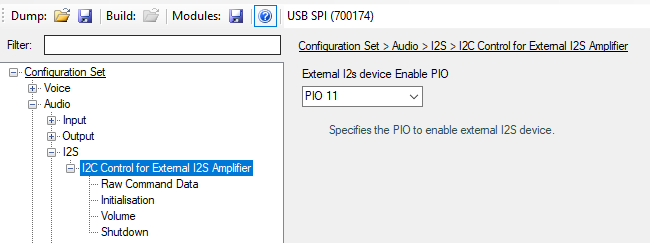
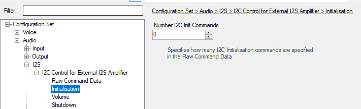
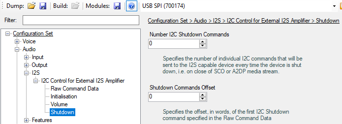
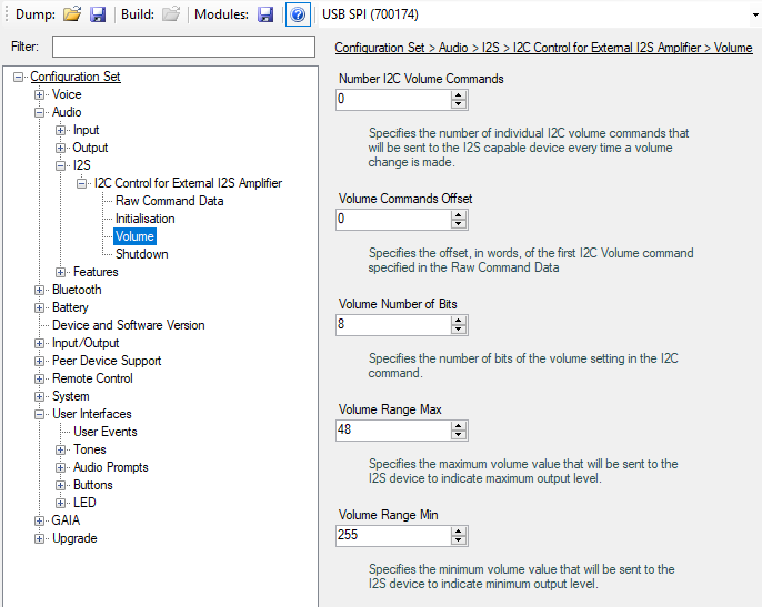
Since the PCM5102A does not have I²C we need to disable all I²C communication, otherwise the CSR8675 gets stuck.
This is done by setting the Number of I²C commands to 0. Also we can configure a ENABLE GPIO which can later be used to automatically soft-mute the DAC via the CSR8675, not using that currently.
Setting that up, the PCM5102A is now appearing in the universal frontend (make sure to have an audio stream running).
Again progress: I was now able to get TWS + I²S running. Background for that requirement is, that I have more than two speakers and would really love to use the internal DSP and crossover of the CSR8675 for both high/mid speakers and one low speaker.
Since the CSR8675 has two differential outputs, I either needed to do crossover work after the fact (either analogue or with a real DSP like ADAU1701) OR I use I²S to get an additional pair of outputs.
I decided for the latter, since it would really save me footprint and effort. An I²S DAC is cheap to have and the implementation and testing is far more straight forward than designing an analogue crossover (which then would have a fixed dropoff frequency) or implementing a custom ADAU1701 solution.
For the testing I now used a PCM5102A on a generic breakout board. Those can be had for pretty cheap. I scored 5pcs for 25€ on amazon.
The PCM5102A is pretty simple. It does not use I²C for configuration, but rather has some Pins that can influence its mode of operation. Rest is determined by the incoming data from I²S.
I went with the following configuration:
FLT -> low
DEMP -> low
XSMT -> high
FMT -> high
This will automatically have the PCM5102A unmuted and waiting for left-aligned data.
Connection to the CSR8765 is made via dunpont connectors, connecting GND, VCC (3.3V), LRCK/SYNC, DIN and BCK. We don't need SCK for this, so that pin can be left open or tied to ground.


There is some configuration to be done inside the ADK Configuration Tool. I am using Version 4.3.15 with the default sink application.
First of all, we need to enable routing of audio to the I²S output channel:

Next is the specific I²S configuration:


Since the PCM5102A does not have I²C we need to disable all I²C communication, otherwise the CSR8675 gets stuck.
This is done by setting the Number of I²C commands to 0. Also we can configure a ENABLE GPIO which can later be used to automatically soft-mute the DAC via the CSR8675, not using that currently.
Setting that up, the PCM5102A is now appearing in the universal frontend (make sure to have an audio stream running).


Using both outputs of PCM5102A for differential signal
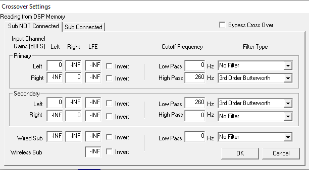
Since in my usecase the PCM5102A will be used to only drive a mono bass channel, I wanted to have that signal ideally differential. The PCM5201A can only output single-ended per channel, but since I do only need one channel, I can use the second one as a inverted output.
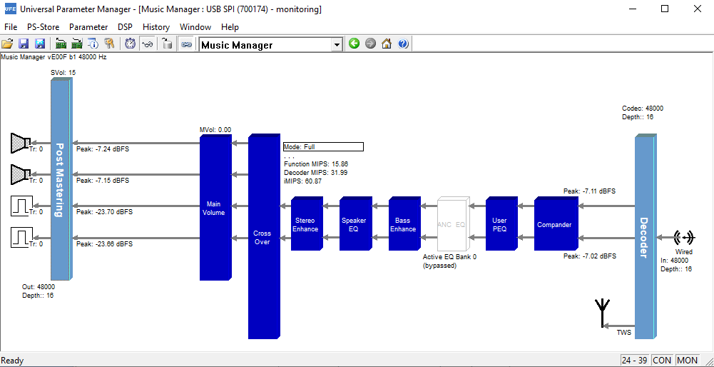
Here is what I did in the UFE (Universal Frontend):

I gave both output channels of the PCM5102A the mixup of the left and right channel (by setting the gain to them for both channels to 0). Then I inverted the second output of the PCM5102A in UFE and voila, we have a nice differential signal:

Hope all this screenshot stuff etc may help others in their efforts using CSR chips.
Since in my usecase the PCM5102A will be used to only drive a mono bass channel, I wanted to have that signal ideally differential. The PCM5201A can only output single-ended per channel, but since I do only need one channel, I can use the second one as a inverted output.
Here is what I did in the UFE (Universal Frontend):

I gave both output channels of the PCM5102A the mixup of the left and right channel (by setting the gain to them for both channels to 0). Then I inverted the second output of the PCM5102A in UFE and voila, we have a nice differential signal:

Hope all this screenshot stuff etc may help others in their efforts using CSR chips.
Hi guys, I found that thread by google and maybe you can bring me the solution of my problem
I want to manage a CSR8675 on a chinese BT module (I2S DAC AptX HD). I used to do this on a QCC3008 before without any problem, but I can not find the SPI enable on the CSR8675 😕😕
With the QCC I connected the 1.8V in SPI enable and 3.3V on the Vbat directly on the chipset like on the picture

I tried several solutions with the CSR, but nothing works, can not connect with the PStool
I start to wire like that

I pray that someone found can help me 😱
Last edited:

this is the new module:
APTX HD CSR8675 adaptateur sans fil Bluetooth 5.0 carte recepteur ES9018 I2S DAC carte decodeur Audio 24Bit/96Khz LDAC avec antenne | AliExpress
The QCC I used before:
Bluetooth 5.0 DAC Module Support APTX Support A2DP AVRCP HFP AAC I2S PCM5102 16M SPI FLASH QCC3008 Home Audio Amplifier|Amplifier| - AliExpress
So there are now images I see.
It appears you use the BTM875-B module, same as I do.
First of all, perhaps you find those two resources useful:
Spec-Sheet:
http://www.tianjiarun.com/zb_users/upload/2020/04/SJR-BTM875-B_SPEC.pdf
Sample-Schematic:
http://www.tianjiarun.com/zb_users/upload/2020/04/SJR-BTM875-B_SCH.pdf
I basically use the following setup:
Connect all SPI pins 1:1 with the CSR programmer:
SPI_CLK
SPI_MOSI
SPI_CSB
SPI_MISO
Power the module:
VBAT_SENSE: 3.3V
VBAT: 3.3V
VDD_PADS: 3.3V
That works a treat for me.
OK so there i only 3.3Volt inputs, that is why I can not connect it with my PStool, I will try your solution, thanks a lot for your help TeHSiggi 😀
Last edited:
It works! I can use PStool, thanks again 😉 Just can not connect with the ADK confirguration tool actually, but I will try to find the solution, the PStool was the most important for my use 😀
What Error message do you get with the ADK tool? AHI version mismatch?
This is likely due to the firmware on the CSR8675 being built with a different version of the ADK than the one you are currently using.
It is definitely worth trying the ADK tool in all available versions (afaik 4.2, 4.4, 4.3.15).
If none of them works, afaik you can only get going by flashing the firmware output of one of those ADK versions to the CSR8675. Anyway, It would be always a wise decision to dump your existing Image with FlashTool and your settings with PSTool, to make sure you can go back at any time.
Hi people!
I'm getting the "error detecting chip type" on PSTool with QCC3008. I suppose I tried everyting, what can I try to make it connect?
Thanks.
I'm getting the "error detecting chip type" on PSTool with QCC3008. I suppose I tried everyting, what can I try to make it connect?
Thanks.
That's a pretty vague description of your problem.
Please post your used hardware, how you connected everything, what version of the ADK you installed etc.
Images also help.
A one liner description like that is like me telling you, that my lightbulb in the kitchen isn't working, although I tried everything. 😉
Please post your used hardware, how you connected everything, what version of the ADK you installed etc.
Images also help.
A one liner description like that is like me telling you, that my lightbulb in the kitchen isn't working, although I tried everything. 😉
Thanks! it's a QCC3008, and I'm using an USB-SBI.
Here the pictures:
I connected the unnamed pin (should be EN) to a 15k ohm resistor then to 3.3v, it's under the heatshrink.


Here the pictures:
I connected the unnamed pin (should be EN) to a 15k ohm resistor then to 3.3v, it's under the heatshrink.
Haven't worked with the QCC3008 boards, especially not with our specific breakout board.
But it appears that the Module you got on your breakout board it the BTM308-C:
http://www.tianjiarun.com/zb_users/upload/2020/04/SJR-BTM308-C_SPEC.pdf
You could use this spec sheet to verify you connection scheme. So measure continuity between the pins on the module and where you connected your programmer, to make sure the connections are right.
Thanks for your reply @TeHSiggi. I don't think the module is the BTM308-C, I looked at the pinout and it have a different number of pins, then the pins marked on the breakout board don't match with the BTM308-C pinout (the chip is marked QCC3008 000 FB934NRH). I know for sure that the module on my board is working with a SPI-USB burner because there is a video on YouTube by @dariee where he connects this module to PSTool (Hooking up the CSR USB SPI Programmer to a QCC3008 Bluetooth Module - YouTube). Unfortunately my breakout board is different from that, even if the module is identical, and programming pins are in a different position. My only doubt, by the way, is about the SPI_EN pin, which has no continuity with any module pin, is this normal? No, right? I also tried to use, instead of the SPI_EN, the SPIPCM pin, but it still give me the error detecting chip type.
My board:


Programmable board:


My board:
Programmable board:
Last edited:
- Home
- Source & Line
- Digital Line Level
- CSR8675 programming guide w software and tons of CSR info