happy daysthis one is mine
are you going to compare the 63 vs 1862?
I always have a teardrop when I think to the first man on Earth who eated an oyster without knowing it must be open...Someone must always be first.
Probably with AD-1865N-Khappy days
are you going to compare the 63 vs 1862?
But I think after this lessons that I took a fake too.

https://www.ebay.com/itm/115301866124
Bah...people already know the pcm63 has a warmer more sexy mid but subjective less bass. That means all of those difference stand in the chip layout and grounding, output impedance, drift of the output current around the said digital zero ? That is above my head. So the ad1862 is 1 mA output and the pcm63 is -4mA output. So even the opa and its Fb resistor wull not work at iso output...be prepared to adjust the volume for a proper listening benchmark.happy days
are you going to compare the 63 vs 1862?
But sure it could be the first time we can compare ad1862 and pcm63 at iso conf parts.
@Vunce : I am confused the rhopoint is not above in your tests. Ayrton perry winding and manganese wires should have an edge ?! But anyway good news for the wallet. But yeah it is subjective...however there are parts that really waste the sound. I am little by little working on caps to try to give with non exotic caps choice a subjective good BOM. Not easy in this standalone opa layout. Thanks Vunce for your feedback.
Last edited:
1862 goes + 1mA to -1mA with 3k you get 2.1 VRMS voltage. If 4mA current is in plus and minus, then the smaller resistor goes, 4x less for the same output voltage. (methinks)So the ad1862 is 1 mA output and the pcm63 is -4mA output. So even the opa and its Fb resistor wull not work at iso output...be prepared to adjust the volume for a proper listening benchmark.
I think Miro is a doctor of science to adjust this.
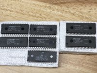
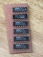
PCM63P
Ok guys, here it is
The output current is 4mA (+-2mA) ==> I/V resistor is the half of the AD1862 for the same output voltage range.
Output capacitor C43 + C44 is optional (it can fight against potentional glitches - first try the sound without this capacitor)
Capacitors C7, C8, C17, C18, C27, C28, C32, C33 can be 100uF-330uF UFG or UKZ, or another high quality audio capacitors.
Capacitors C15, C16, C25, C26, C37, C38 also a high quality audio capacitors, can be larger value as in datasheet (you can do some experiment with different values, also you can install parallel some 0805 SMD C0G 47nF MLCC from the bottom (like C0805C473J8GACAUTO)) ... Try 47uF UKZ or UFG.
PCB contains pins for optional MSB adjustment circuitry, in that case C39 - C42 will not be installed, or can be? (datasheet page 8) -- I did not place parts on the PCB for this circuitry - hard to recommend this procedure bacause of adjustment difficulty.
BOM example: https://www.mouser.com/ProjectManager/ProjectDetail.aspx?AccessID=b640758624
Note: Very experimental PCB, it may not work at all (sorry for any errors) ... it is also difficult to get the PCM63P for testing, the same situation as with the TDA1541A
Attachments
-
diyAudio_PCM63P_DAC_v1.4_uf.l_2022-06-15.zip713.6 KB · Views: 203
-
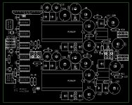 diyAudio_PCM63P_DAC_v1.4_uf.l_Parts.jpg269.7 KB · Views: 663
 -
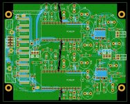 diyAudio_PCM63P_DAC_v1.4_uf.l_PCB.jpg503.7 KB · Views: 849
 -
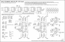 diyAudio_PCM63P_DAC_v1.4_uf.l_Schematic.jpg431.6 KB · Views: 899
 -
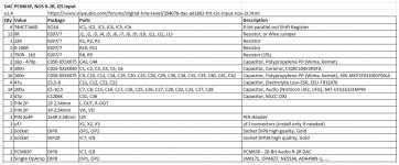 diyAudio_PCM63P_DAC_v1.4_uf.l_BOM.jpg149.3 KB · Views: 818

Certainly a 1865 with a an added K if bougth on Ali. Do not buy milk for babies as well on Ali or TobaoProbably with AD-1865N-K
But I think after this lessons that I took a fake too.
https://www.ebay.com/itm/115301866124
Last edited:


There could be TDA1540 and TDA1541A right afterThanks again Miro! The week is not over yet, another surprise hiding up your sleeve?
Looks like the old stash will get put to work
But first I need test the input logic for these chips PCB contains pins for optional MSB adjustment circuitry, in that case C39 - C42 will not be installed, or can be? (datasheet page 8) -- I did not place parts on the PCB for this circuitry - hard to recommend this procedure bacause of adjustment difficulty.
My Sith dark lord friend sent me to look at this. But I'm just Youngling
- Home
- Source & Line
- Digital Line Level
- DAC AD1862: Almost THT, I2S input, NOS, R-2R