If anyone would want to use the +/-12V supply from the DAC for a discrete JFET IV and accept the PSU crosstalk with the IV converter, output caps, etc.
I suggest you have a serious look at Nelson Pass's Zen IV :
https://www.passdiy.com/project/other/zen-i-v-converter

Full details at the link above.
You do not need 30V rails and it works perfectly fine with 12V if you use GR grade JFETs and your DAC has +/-1mA Iout, as in AD1862.
A matched quad of K170/J74 GR (for 2x IV converters) costs 33 USD from ebay dealer punkydawgs recommended by Nelson himself.
Just search for : Toshiba 2SJ74 LAB MATCHED QUAD to 0.03mA / 4mV (4.0 - 6.0 mA Range) "GR"
If you can get 4mA Idss, you can even increase Riv (R3,4) to 1.5k.
You can build this for less money than a single OPA627, or some fancy discrete opamp.
Also costs much less than the FC CEN IV, but of course that is for very good reasons.")
Cheers,
Patrick
I suggest you have a serious look at Nelson Pass's Zen IV :
https://www.passdiy.com/project/other/zen-i-v-converter
Full details at the link above.
You do not need 30V rails and it works perfectly fine with 12V if you use GR grade JFETs and your DAC has +/-1mA Iout, as in AD1862.
A matched quad of K170/J74 GR (for 2x IV converters) costs 33 USD from ebay dealer punkydawgs recommended by Nelson himself.
Just search for : Toshiba 2SJ74 LAB MATCHED QUAD to 0.03mA / 4mV (4.0 - 6.0 mA Range) "GR"
If you can get 4mA Idss, you can even increase Riv (R3,4) to 1.5k.
You can build this for less money than a single OPA627, or some fancy discrete opamp.
Also costs much less than the FC CEN IV, but of course that is for very good reasons.
Cheers,
Patrick
Last edited:
Slight detour from the current topic and some need for support.
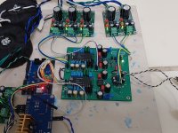
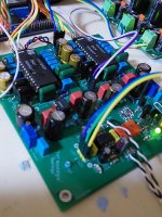
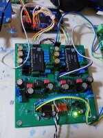
I finished a PCM63 DAC and am trying to make it work with JLSounds v.3.
I connected it as per the User Manual and post https://www.diyaudio.com/community/...st-tht-i2s-input-nos-r-2r.354078/post-6828113 and there was no sound.
So I pulled the oscilloscope and started measuring JSSounds output at BCK/LRCK pins.
This is without J4 and the resistor between pins 1 and 3 on H5 - there are 32 BCK per 1 LRCK:

This is without J4 but with a 5.6K resistor (Lyuben from JLSounds said it would work - I don’t have 4.7K at the moment) - 24BCK/LRCK:

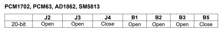
And this is how it is expected to be set up: J4 closed and 5.6K resistor - there are 20 BCK/1LRCK:

And finally, for the last case, an Image with time division compressed that shows the whole picture: per one full period there are 32 BCK and they are distributed 20 HIGH + 12 LOW.

Disclaimer: I haven’t used oscilloscope for about 30 years - and this was within the Physics curriculum, not engineering. So I’m not sure I’m setting up everything as I should.
My question is - in the PCM63P data sheet, it reads that the word is 20 bit and it latches on LOW. What (I think) I’m seeing is that the 20 bits are on HIGH.
What am I missing? Any links to some info I can read before I start asking educated questions?
I finished a PCM63 DAC and am trying to make it work with JLSounds v.3.
I connected it as per the User Manual and post https://www.diyaudio.com/community/...st-tht-i2s-input-nos-r-2r.354078/post-6828113 and there was no sound.
So I pulled the oscilloscope and started measuring JSSounds output at BCK/LRCK pins.
This is without J4 and the resistor between pins 1 and 3 on H5 - there are 32 BCK per 1 LRCK:
This is without J4 but with a 5.6K resistor (Lyuben from JLSounds said it would work - I don’t have 4.7K at the moment) - 24BCK/LRCK:
And this is how it is expected to be set up: J4 closed and 5.6K resistor - there are 20 BCK/1LRCK:
And finally, for the last case, an Image with time division compressed that shows the whole picture: per one full period there are 32 BCK and they are distributed 20 HIGH + 12 LOW.
Disclaimer: I haven’t used oscilloscope for about 30 years - and this was within the Physics curriculum, not engineering. So I’m not sure I’m setting up everything as I should.
My question is - in the PCM63P data sheet, it reads that the word is 20 bit and it latches on LOW. What (I think) I’m seeing is that the 20 bits are on HIGH.
What am I missing? Any links to some info I can read before I start asking educated questions?

Datasheet contains all the info you need:What am I missing? Any links to some info I can read before I start asking educated questions?
The serial-to-parallel data transfer to the DAC occurs on the falling edge of Latch Enable (P20, LE). The change in the output of the DAC coincides with the falling edge of Latch Enable (P20, LE).
Any number of bits can precede the 20 bits to be loaded, since only the last 20 will be transferred to the parallel DAC register after LE (P20, Latch Enable) has gone low.
The actual duty cycle of LE (LRCK) is not relevant as only the falling edge matters. LE needs to stay high/low for one clock cycle after changing state.
Another version evolved from the Pass design above (post #6281) is the one from Spencer here :
https://www.diyaudio.com/community/threads/zen-i-v-converter.173291/post-6925506
This is an earlier but complementary push-pull version of that posted here a few days ago.
The intelligent bit is C8/C11 to reduce distortion significantly (see original post).
And it has actually been built and measured. PCBs also available.
https://www.fetaudio.com/archives/date/2022/01
Still capacitor coupled at the output, power rail referenced, and low iv conversion gain (<1V output / 1mA signal current).
Patrick
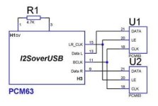
@Brijac I should have been more clear: I am not using the shift registers - I am connecting directly to DL and DR.Jump it like this. Also, update to the latest firmware.
View attachment 1152683
Also, the instructions for updating the firmware claim that the last driver supporting PCM1704 protocols is 3.60.
Anyone here with success with direct JLSounds -> PCM63P?
@miro1360 thank you for the info. This is exactly what I initially did and heard no sound.
Only then I started debugging with the oscilloscope, etc.
I’ll try with shorter wires - mine were about 20cm for the “smoke test”.
Thanks to Miro, my TDA1540 nostalgic DAC is working 15mins ago. Will let it run to warm up a few hours and then listen. Immediate impression is this DAC has the balls LOL...
Attachments
@skrstic i belive did it without shift registers. He can shed some light how he managed to get it working.@Brijac I should have been more clear: I am not using the shift registers - I am connecting directly to DL and DR.
Also, the instructions for updating the firmware claim that the last driver supporting PCM1704 protocols is 3.60.
Anyone here with success with direct JLSounds -> PCM63P?
Everything has been said in the previous posts.@skrstic i belive did it without shift registers. He can shed some light how he managed to get it working.
I have shifters now, but I think I liked the sound better without them. I'll have to chop little and try without them.
Great, I'm very happy that everything works, especially the tutorial for the I2S converterThanks to Miro, my TDA1540 nostalgic DAC is working 15mins ago. Will let it run to warm up a few hours and then listen. Immediate impression is this DAC has the balls LOL...
How do you find TDA1540 bass? Ofcourse, this is one very good circuit. Unfortunately those FETs imported for me cost over a 100$ due to local customs and tax.If anyone would want to use the +/-12V supply from the DAC for a discrete JFET IV and accept the PSU crosstalk with the IV converter, output caps, etc.
I suggest you have a serious look at Nelson Pass's Zen IV :
https://www.passdiy.com/project/other/zen-i-v-converter
View attachment 1152638
Full details at the link above.
You do not need 30V rails and it works perfectly fine with 12V if you use GR grade JFETs and your DAC has +/-1mA Iout, as in AD1862.
A matched quad of K170/J74 GR (for 2x IV converters) costs 33 USD from ebay dealer punkydawgs recommended by Nelson himself.
Just search for : Toshiba 2SJ74 LAB MATCHED QUAD to 0.03mA / 4mV (4.0 - 6.0 mA Range) "GR"
If you can get 4mA Idss, you can even increase Riv (R3,4) to 1.5k.
You can build this for less money than a single OPA627, or some fancy discrete opamp.
Also costs much less than the FC CEN IV, but of course that is for very good reasons.
Cheers,
Patrick
@miro1360,
Is not easy to screw things up using your simple and clear tutorial. I simply follow the steps like a dummy. If a dummy like me can follow the programming steps, I believe anyone who can use a PC will be successful in the project. 🤣
I agree with your comments earlier that this DAC really packs a punch in the bass. Real deep solid and tight bass. Has a very life-like quality in the vocals. Sounds more forward, in-the-face than the Ad1862. A very different animal compared to AD1862. Currently using opa627, I would like to experiment with others to try to achieve more air and extensions in the higher notes which I get from the Miro 1541. I am very happy with what I am hearing at this point though.
Last edited:
Ofcourse, this is one very good circuit. Unfortunately those FETs imported for me cost over a 100$ due to local customs and tax.
The reference to the ZEN IV, as with my other posts on the subject, was meant for the general public and not at any particular person(s).
There are also many other discrete IV circuits one can build, also using the +/-12V supplies, using components readily available.
Here are only a few examples :
https://www.diyaudio.com/community/...urrent-mirror-iv-converter-a-la-ad844.360162/
https://www.diyaudio.com/community/...st-tht-i2s-input-nos-r-2r.354078/post-7265124
https://www.diyaudio.com/community/...st-tht-i2s-input-nos-r-2r.354078/post-7264825
Cheers,
Patrick
- Home
- Source & Line
- Digital Line Level
- DAC AD1862: Almost THT, I2S input, NOS, R-2R