But yes noise could be the issue. So I am positive that minimum 2X CL filtering is a must, Maybe a 3X. After rectifier tube (off course) 🙂
A little distortion never hurt anyone.But some members use 200ohm or more inspired of these facts... Again, sound is good...
D3a is good (large output swing) VAS tube too.D3a TFK or Siemens when NOS are excellent. ...
For these conditions of small input signal range of say 0.05 Vp-p and say 70X output 3.5Vp-p distortion of very linear tube, with good choice of most linear region distortion can be very very small.
It is not driver tube giving a voltage all over the HV region and huge -Ug values and currents.
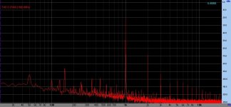
Sample: 70VRMS (about 198Vpp) driver FFT.
It's enough even to driving 211 (via CF or SF).

I did tests with PCM1702, unfortunately not with TDA1541. I kept the 100R for years until I remembered to try a lower value. First I went to 75R and got a wow and then 50R and an even bigger wow 🙂If you split a Wooki fur in 4 you certainly can use 35R and please your scope... but will you hear the difference with a late ECC88 ?
I doubt.
The difference in the sound was really noticeable especially with the 50R, the tube used was the 6S4P.
If it is an ECC88 and a current of +/-1mA(AD1862) and if we use only 25R for the Riv, the output voltage will again be 1.3Vp-p which will be quite enough for someone who has a preamp in the system. TDA1541 with the same Riv will have 2.6Vp-p with ECC88.
I don't have a preamp, so I drive the amplifier directly with the DAC, and that's the reason why I use tubes with a higher gain, 6S4P and now 6HM5 with a mandatory output buffer. However, as two more PCM1702s are arriving soon, so the ECC88 comes into play again, with four PCMs I could have an output voltage of 4Vp-p to 7Vp-p with a lower THD.
It's equivalent of D3a.
I used both.
Some schematic please if possible, just to see.
I have a liitle stash of E280F.
and then 50R and an even bigger wow
Keep going down to 20R and the wow is even bigger, which is of course no surprise. 🙂
With 20R, you get 14mVrms out. So you need gain of 140x downstream.
But any phono preamp without the RIAA correction (also solid state ones) can do that.
At least that is what I would do if I have to use passive IV.
Patrick
Oh, forgot to mention if you want to use ICs, an AD8429 will do 140x in a single chip with ease.
THD ~ -110dB.
Patrick
THD ~ -110dB.
Patrick
Little? The wave form is deformed a lot, stepping into the clipping... 😕A little distortion never hurt anyone.
I want to point huge differences in operation of tube used in IV circuit compared to other modules. In IV tube operates in very small region of any value. I didn't have time to make the graphical explanation which will be more clear... 🙂 sorry.D3a is good (large output swing) VAS tube too.
Sample: 70VRMS (about 198Vpp) driver FFT.
It's enough even to driving 211 (via CF or SF).
View attachment 1096368
.
For instance in driver stage tube working in maybe more than "full" swing. The problem is that D3a has very low values of -Ug for driver tube.
For this 198Vp-p divided with -A say 65-70 (in circuit it is smaller than mju of 77) -Ug p-p has to be 3V. This is for 1/2Ugp-p bias of -1.5V...
And of course output resistance and needed current output should be taken into account...
...
CF is another thing no gain and no phase shift, in IV stages Anode follower is used
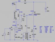
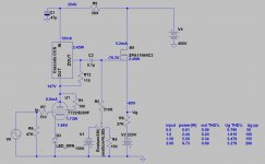
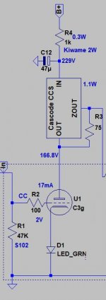
D3a/E280F, CCS loaded VAS stage, FET source follower (SF).Some schematic please if possible, just to see.
I use its in my daily used 300B amp, with -a little- different tone.
E280F more refined, D3a more "HiFi", but both of very good, and "enough" to drive 300B or 211, even in A2.


I tested D3a in phono, but there I more prefer E810F (with a little lesser gain), or C3g.
Sample phono first stage:

Last edited:
 Complaints received about pulling thread off topic which is AD1862 related. If you wish to discuss other D/A converters (encouraged) please start a new thread to do so.
TDA1541A discussion moved to this thread: https://www.diyaudio.com/community/threads/tda1541a-dac-project-discussion.390927/
Last edited:
I am interested in making the AD1862 DAC. Thanks to Paddy for selling me some boards and DAC chips. I have added it to the Queue of DACs I am building (Soekris Dam 1021, AK4493)
Hi, guys. I have a some trouble with 1862 DAC. He's start to wheezing but at first there was a squeak. I was tried to change opamps on 797 (I have a pair) - I was heard a liitle squeak on min volume. I have a sound and there is no problem - I still can listen to music.
This incident has started after non working amp (Audio Analogue) which they brought to me and didn't tell me about that. He has a strong wheeze and there is no sound. I turned off right away and never turned it on again. That's what happened with my DAC.
What might have happened? I also speak with some people about my problem and they recommended to change opamps on 604 and also check the details after chips.
Judging by schematic, J5 and J6 jumper not jumped with a connection to 5V, and VA slots are for V12 then? Always like to double check 😁
Be careful here. Paralleling DACs does not increase the signal voltage amplitude, while maintaining the level of distortion. Since the passive I/V distortion is a function of the signal voltage amplitude developed at the current output pin of the DAC chip, increasing the voltage amplitude at that pin increases DAC distortion. To make effective use of paralleled DACs with a passive I/V requires reducing the value of the I/V resistor by the same factor as the number of paralleled DACs. Parallel two DACs, then divide the I/V resistor by a factor of 2. Four DACs, then by a factor of 4....However, as two more PCM1702s are arriving soon, so the ECC88 comes into play again, with four PCMs I could have an output voltage of 4Vp-p to 7Vp-p with a lower THD.
The result is no increase in signal voltage amplitude at a given level of distortion. The I/V stage's output impedance, however, goes down by the same factor as how many DACs you have paralleled. Aside from the reduction of random noise, and a certain type of resistor based DAC chip quantizer non-linearity, and which, by far, are the primary benefit from paralleling DAC chips. Paralleling DAC chips does potentially enable the I/V stage to directly drive the output line connecting the DAC box to the next box in the signal chain (preamplifier or power amplifier), without an additional output amplification stage. Assuming , of course, that the limited signal voltage available from a resistor I/V is of sufficient amplitude. Which in most instances, I suspect that it won't be.
- Home
- Source & Line
- Digital Line Level
- DAC AD1862: Almost THT, I2S input, NOS, R-2R