I found some information.
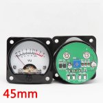
The popular specification of VU meter is 650 ohm/500 uA, but only can connect to the 50W output like attached photo. but the TAS3251 is 175W.
And if it is connect to the TAS3251 output, it will be distort by volume up/down.
If I want to create my own circuit with the 650ohm/500uA meter, What can i do?
have any drive IC can use for it?
thanks.
Attachments
PreAmp
As I’m happy with the result, NeatAmp will become my main amp in the living room. It will be boxed in a large 2U Galaxy enclosure with the smps, a soft start and a preamp.
Preamp will have 7 inputs : 2 spdif, 2 toslink, 2 Bluetooth (1 open and 1 dedicated for a bridge with the tv), and 1 usb (44.1/48k-16bits). It will also have an IR receiver, an OLED display and one or two rotary encoder. It will mainly be build around a STM32F303, a AK4118 and two CSR Bluetooth modules.
Preamp will interact with NeatAmp and manage it trough serial link, so a new but simpler NeatAmp software should be written. NeatAmp uC will manage low level TAS3251 function and Preamp uC will manage UI and the various I2s stream sources.
Preamp is made of three boards, one for the rear panel with the inputs connectors ; one for the front panel for the display, the IR receiver and the encoder ; and one for the main board ; all three connected via flat cables.
Currently the pcb are somewhere between Shenzhen and home, I should be able to start first test on the softstart end of August, back from vacation...
Waouh, your summer was more productive (amp wise) than mine ;-)
I'm really happy to see that usage of the NeatAmp in a larger project. This was the initial intention: a versatile digital and powerfull (Watts) audio brick, to use as a part of larger and more specific projects.
Did you opened a thread for tha new project ?
JMF
I'm really happy to see that usage of the NeatAmp in a larger project. This was the initial intention: a versatile digital and powerfull (Watts) audio brick, to use as a part of larger and more specific projects.
Did you opened a thread for tha new project ?
JMF
I made a mini TAS3251 PCBA with an MCU, and I used TI-TAS3251-EVM with PPC3 software to generate a ".h" file
May I know this ".h" file have a writing sequence from MCU to TAS3251 through I2C interface?
ex:
1.program memory >> 2.Sample rate update >> 3.dynamically reading speed >> 4.write co-efficients >> 5. ......
For currently,
I write EQ setting into mini TAS3251 from PPC3 (PC) directly, the sound is good.
But the sound is abnormal if I write EQ(.h) into mini TAS3251 through MCU.
thanks.
Last edited:
There is a basic sequence but it is embedded into the construction of the .h file by PPC3, so you should be able to load the .h line by line. As described in the datasheet TAS require a short delay after clock setup and before DSP coefficient loading. Thus, you may encounter issues with .h loading into the TAS when running I2C at 400kHz, it’s safer to run you design/setup/debug steps at 100kHz, at 400kHz the expected delay may not be reached.
Having a ‘bad’ sound is good…much better than no sound !, I did encounter no sound for long while debugging my software, this was mainly caused by loading issues in relation with loading speed and status of MUTE pin while loading DSP coefficient.
Having a ‘bad’ sound is good…much better than no sound !, I did encounter no sound for long while debugging my software, this was mainly caused by loading issues in relation with loading speed and status of MUTE pin while loading DSP coefficient.
If you properly implement the code that is commented out in the top of the header file, the delay is not dependant on the writing speed.
@knee
You should first write your header file. After that you can re-write biquads while running. Make sure you are on the correct book and page when writing to biquad registers.
@knee
You should first write your header file. After that you can re-write biquads while running. Make sure you are on the correct book and page when writing to biquad registers.
Hi,
I'm facing problems with pop noise after the startup procedure with my own build of the tas3251 amp. When I transferred the parameters of the .h file via i2c and then pull the reset_amp pin high I get a little pop in the speakers.
I assembled the c_start capacitor as 33 nF at first and then tried 100 nF which made the pop issue a bit quieter. I could increase up to 470 nF (as the datasheet says), but I'm not sure if there is another solution.
Has anyone had comparable issues with the startup of the amp?
There is a basic sequence but it is embedded into the construction of the .h file by PPC3, so you should be able to load the .h line by line. As described in the datasheet TAS require a short delay after clock setup and before DSP coefficient loading. Thus, you may encounter issues with .h loading into the TAS when running I2C at 400kHz, it’s safer to run you design/setup/debug steps at 100kHz, at 400kHz the expected delay may not be reached.
Having a ‘bad’ sound is good…much better than no sound !, I did encounter no sound for long while debugging my software, this was mainly caused by loading issues in relation with loading speed and status of MUTE pin while loading DSP coefficient.
This is a good idea, thanks for your advice.
I will try to use 100KHz to programming TAS3251.
Hi,
I'm facing problems with pop noise after the startup procedure with my own build of the tas3251 amp. When I transferred the parameters of the .h file via i2c and then pull the reset_amp pin high I get a little pop in the speakers.
I assembled the c_start capacitor as 33 nF at first and then tried 100 nF which made the pop issue a bit quieter. I could increase up to 470 nF (as the datasheet says), but I'm not sure if there is another solution.
Has anyone had comparable issues with the startup of the amp?
When the power is turned on, maybe you can try to pull RESET_AMP to high first, then pull up DAC_MUTE.
Hello~
I found that AIM65 only writes a few co-efficients into TAS3251, not the complete .h file of PPC3.
I output a .h file from PPC3, and then write the .h file from MCU to TAS3251. But the sound is not the same as writing directly from PPC3.
(I have purchased TI TAS3251 EVM board)
I have tested it for a long time and the result is the same. Does anyone know the reason?
thanks.
Attachments
They’re mainly two parts in the .h file (I leave the commented section with code example); one for the coefficients of the DSP (the coefficients, which are mainly in Book 0x8C) and one the configuration of the various module such as clocking, some volume control, basic signal path, muting, …. There’s nothing for the Class D stage which is obviously a separate dice installed in the chip package.
My software on github manage both separately and by default contains no coefficient nor config data. But there’s an example .h file which contains very few coeff : some volume related one’s if I remember correctly. This is a basic test .h file.
About your issue some way to look at :
Chris
My software on github manage both separately and by default contains no coefficient nor config data. But there’s an example .h file which contains very few coeff : some volume related one’s if I remember correctly. This is a basic test .h file.
About your issue some way to look at :
- First you have some sound : this is encouraging !
") , I spent many time without sound while debugging !
, I spent many time without sound while debugging ! - Is there’s a difference between cold start and warm restart ? (this allows to confirm efficiency of soft reset which occurs at the beginning of the .h file with { 0x01, 0x11 }, command.
- EVM has an SRC on board, do you feed TAS on the EVM (after SRC) with the same sampling frequency than on your prototype ?
- If you have sound that’s means your config data are loaded ok and either your coeff date are not loaded or your coeff data are error free but do not execute what you expect (see above, the point about sampling frequency, the TAS has no internal SRC, that means that the coeff have to be recalculated for each sampling frequency used.) . When I say error free, that mean that a well loaded coefficient but with bad values could mute sound. 'No sound' issue may have many different causes.
Chris
They’re mainly two parts in the .h file (I leave the commented section with code example); one for the coefficients of the DSP (the coefficients, which are mainly in Book 0x8C) and one the configuration of the various module such as clocking, some volume control, basic signal path, muting, …. There’s nothing for the Class D stage which is obviously a separate dice installed in the chip package.
My software on github manage both separately and by default contains no coefficient nor config data. But there’s an example .h file which contains very few coeff : some volume related one’s if I remember correctly. This is a basic test .h file.
About your issue some way to look at :
I will have a look to your .h file at lunch time, and look for any useful idea
- First you have some sound : this is encouraging !
- Is there’s a difference between cold start and warm restart ? (this allows to confirm efficiency of soft reset which occurs at the beginning of the .h file with { 0x01, 0x11 }, command.
- EVM has an SRC on board, do you feed TAS on the EVM (after SRC) with the same sampling frequency than on your prototype ?
- If you have sound that’s means your config data are loaded ok and either your coeff date are not loaded or your coeff data are error free but do not execute what you expect (see above, the point about sampling frequency, the TAS has no internal SRC, that means that the coeff have to be recalculated for each sampling frequency used.) . When I say error free, that mean that a well loaded coefficient but with bad values could mute sound. 'No sound' issue may have many different causes.
Chris
Hello AIM65,
Most of this is the result of your research, which shortened my research time,thank you very much
There is no difference between cold start and warm restart, but the sound is not the same as writing directly from PPC3.
EVM has an SRC on board, do you feed TAS on the EVM (after SRC) with the same sampling frequency than on your prototype ? << YES
If there are any suggestions, I will try, thank you
Hello knee266,
Could you describe a bit more the difference in sound that you hear ?
Is one "inconsistent": there is sound, but not really you music, or highly distorted ?
Is it a subtle difference, like some additional filtering (without bass, or without trebbles)...
Other hints at the difference ?
You can get music from the TAS3251 already with a minimal config to start the different stages, keeping everything else with default values.
One exemple is NeatAmpTAS3251/TAS3251.h at master * jmf13/NeatAmpTAS3251 * GitHub
1) I would start tests with that and achieve the same sound in both configs between those 2 configurations.
2) I would try to "reread" the values I have written, to check that the writing was successful (I had some surprises like that in my debugging process)
3) There is a critical timing in the set-up sequence (thanks AIM65 to have discovered that). You need to wait for the DSP to start. Example below:
// Config LXmini Davey LR4
cfg_reg registers[] = {
//program memory
{ 0x00, 0x00 },
{ 0x7f, 0x00 },
{ 0x02, 0x11 },
{ 0x01, 0x11 },
{ 0x00, 0x00 },
{ 0x00, 0x00 },
{ 0x00, 0x00 },
{ 0x00, 0x00 },
{ 0x03, 0x11 },
{ 0x2a, 0x00 },
{ 0x25, 0x18 },
{ 0x0d, 0x10 },
{ 0x02, 0x00 },
{ 0x00, 0x00 }, // for delay for DSP config
{ 0x00, 0x00 },
{ 0x00, 0x00 },
{ 0x00, 0x00 },
{ 0x00, 0x00 },
{ 0x00, 0x00 },
{ 0x00, 0x00 },
{ 0x00, 0x00 },
{ 0x00, 0x00 },
{ 0x00, 0x00 },
{ 0x00, 0x00 },
{ 0x00, 0x00 },
{ 0x00, 0x00 },
{ 0x00, 0x00 },
{ 0x00, 0x00 },
{ 0x00, 0x00 },
{ 0x00, 0x00 },
{ 0x00, 0x00 },
{ 0x00, 0x00 },
{ 0x00, 0x00 },
{ 0x00, 0x00 },
{ 0x00, 0x00 },
{ 0x00, 0x00 },
{ 0x00, 0x00 },
{ 0x00, 0x00 },
{ 0x00, 0x00 },
{ 0x00, 0x00 },
{ 0x00, 0x00 },
{ 0x00, 0x00 },
{ 0x00, 0x00 },
{ 0x00, 0x00 },
{ 0x00, 0x00 },
//Enable sub channel
// YM host buffer
{ 0x00, 0x00 },
{ 0x7f, 0x8c },
//prm_nosub
{ 0x00, 0x1d },
{ 0x28, 0x00 },
{ 0x29, 0x00 },
{ 0x2a, 0x00 },
{ 0x2b, 0x00 },
To have basic sound output without any filters you just need 5 - 7 pairs of addr and data to send to the tas3251, exactly as it's mentioned in the datasheet:About your issue some way to look at :
[*]First you have some sound : this is encouraging !
Code:
cfg_reg registers[] = {

    //Switch to Book 0
    { 0x00, 0x00 },
    { 0x7f, 0x00 },

    /*
    //reset sequence - not necessary except developing
    { 0x02, 0x11 },
    { 0x01, 0x11 },
	//wait
    { CFG_META_DELAY, 5 },
     */

    //mute dac
    { 0x03, 0x11 },
    //ignore mclk error and clock halt detection, because I don't use the mclk input pin
    { 0x25, 0x18 },
    //therefore PLL reference clock must be SCLK
    { 0x0d, 0x00 },

    //set dsp to normal operation
    { 0x02, 0x00 },

    //Unmute the device
    { 0x03, 0x00 },
};Normally there is no "warm" start except for reflashing the firmware of the uC while developing and debugging. So no reset needed.[*]Is there’s a difference between cold start and warm restart ? (this allows to confirm efficiency of soft reset which occurs at the beginning of the .h file with { 0x01, 0x11 }, command.
Interesting, I expected there must be some kind of src in the tas3251. At least that is what I expected from a quick look at the[*]EVM has an SRC on board, do you feed TAS on the EVM (after SRC) with the same sampling frequency than on your prototype ?
process flows overview. There it says:
- SRC (2x decimator) 96 -> 48 and 88.2 -> 44.1
Now I realized that the amp is not capable of converting to another clock base e.g. from 48 khz to 44.1 kHz. That is really annoying.
TI did totally non-sense with that wait cycles in tas3251. The time duration is inconsistent and depends on the used i2c clock. I can't imagine why they didn't use the "CFG_META_DELAY" option as they did in the tas5825m. They could have done so with tas3251. I'd recommend to use that instead of sending zeros via i2c.3) There is a critical timing in the set-up sequence (thanks AIM65 to have discovered that). You need to wait for the DSP to start. Example below:
I think TI created a total mess with the tas3251. Why didn't they just took the core of tas5825m and adopted it to the higher output power...
Instead they tried to take the tpa3251 and tinker some dsp and dac around.

- Home
- Amplifiers
- Class D
- [design log] Neat 2x170W I2S in, I2C controlled, integrated DSP amp (TAS3251)