Another Dutchie-DX 
I can't offer experience using other transistors, since i have only used 2n5401(differential) and bd139/bd243c/244c (vas/drivers).
In my experience there shouldn't be distortion using bias below 100 mA, even at ~20mA sound was fine on my DX.
As Carlos has pointed out, there must be a mestake or something wrong with your-operating-points of the transistors.
Also your noises are cause of concern, i don't notice any noise exept a faint hiss when i put my ear upclose to the tweeter, but this is coming from my pre-amp (all power-amps hooked up to it have this hiss)
If you need any assistance, my e-mail through the forum is enabled
Groeten uit Leeuwarden,
Klaas
hi Carlos,
As you had said that DX Amp will operate on 35V plus and 35V minus as based on the existing design, will it work fine if i will used two pair of output transistors? What is the resistance and wattage for the resistors to be used on its emitters? Will the bias cureent still in 50 mA at +/- 35 Volts supply?
I just ask this because I believed that adding additional pair of output transistor will make this amp runs cooler.
About the output coil, could it give safety to the amp? How about the sonic quality, is there any implication on installing this coil? If there is a deviding network installed on the speaker system used, is there any precaution to be taken?
Sorry if this a silly question, but I just want to have knowledge about audio amplification and reproduction. And safety of the amplifier as long as the user is my main concern.
I hope that you will not get bored with me man. Even you feel this way, but I salute you man. By the way, I am wondering why you called yourself a distroyer instead you are a creator. And also to Mr. Graham Mynard, I am so thankful for the knowledgeable inputs on the forum.
Regards,
Bernhix
Hi Inex,
I wonder about your PSU and LS wiring, also heatsink grounding.
The pcb must be the common grounding point for all.
What is that thin green/white coming out of the amplifier for ?
Hi Berhnix,
No mistakes (which with SS = no destruction) = no learn.
Cheers ...... Graham.
I wonder about your PSU and LS wiring, also heatsink grounding.
The pcb must be the common grounding point for all.
What is that thin green/white coming out of the amplifier for ?
Hi Berhnix,
No mistakes (which with SS = no destruction) = no learn.
Cheers ...... Graham.
2 resistos on VBE? and what is the thick grey wire running underneath the board...
My earth is as follows... Mains earth connected to ground tab on transformer caseing and from there goes to earth disconnect network together with centretap's wire..
After the network, is one wire going to a the PSU ground input spade...
one wire froum PSU output spade to lug bolted into the heatsink...
From the lug, runs the wire that plugs into the amp's earth spade... and also the speaker earth wire... on the amp board self Elinks bridged, and thick solid wire from ZE out to base of ground spade, between the 220uf and 47uf cap in the middle is convenient place to route that wire...
I am not aware of any PSU noise with this setup... mine is silent as a rock.
Thank you folks...you are helping a lot...Klaas, Graham and Nordic.
To Inex
The vbe multiplier use one resistance from colector to base (1K8, 2K or 2K2)..and a trimpot from base to emitter (1K adjusted around 666 ohms).... each circuit may need a different adjustment., because different transistors and different supply voltages.
Those modifications just turn the adjustment easier... reducing that critical situation when you move the trimpot 5 degrées and result in big change in current.
The best sittuation is to substitute the 1K trimpot by a more adequated series of resistances..one fixed and another trimpot value to allow you easier adjustment..but this depends on first set up and them you will conclude.
For instance...if you discovered that 666 ohms adjusted the current to a nice value...than you can substitute the trimpot by a 560 ohms in series with a 200 ohms trimpot...than, you will have a fine adjustment possibility.
Not possible to give a fixed "universal" value, as this is not a kit...you will use your prefered transistors and also the supply you have...so....universal values will not fit.
regards,
Carlos
......................................................................................................
Yes Bernix
You can use more parallel Trs.... sonic qualities goes to.... sound use to turn blurred..as they are never the same.
Using more transistors you will divide heat into a big heatsing...distributing better the "heat generators"..those transistors.... but will not make the heatsink bigger as needed sometimes
The emitter resistances can be 0.47 ohms, 0.33 ohms or 0.22 ohms...i prefere the smaller one.
Using more parallel you will able to install more speakers in parallel...the maximum power can reach 200 watts RMS...but this..if your supply was strong enougth to keep the voltage stable under severe loading sittuations (not normal to keep voltage stable under those conditions...need a bigger trafo.)
Coil is a need for professional purposes, as using a long cable you will be producing and antenna...an aerial....20 meters of cable may tune 7 Megahertz..so...nearby stations or generator of radio frequency may disturb..some medical equipment too.
The radio frequency crossing your speaker cables will convert magnetic energy into electrical energy.... this will enter the amplifier output and will smoke your amplifier very fast... before you say "hey!"
Also long lengthes of speaker cables will produce capacitance..measured by meters long....and capacitance in the output use to unstabilize every amplifier..not only Dx amplifier.
Also speakers that use terrible coils inside...awfull capacitor and very ugly resistances inside will be an amplifier assassine...a killer to the amplifier..... so...using those coils in the output you will be "more" protected against those problems...it will not keep you safe...just will protect you a little.
Better not to use 20 meters of speaker wire...not to be near strong radio frequency generators or transmitters...not to use those speakers too...by passing the crossover..let only the series capacitors to the tweeter and Mid ranges..and they are hell enougth.....do not make more monsters to eat your amplifier.
You do not bother me.... go ahead and ask everything you want or need...if i was able you will have answer..if not i will call help for my thread friends..as i have no problems to do that.
regards,
Carlos
bernhix said:I just ask this because I believed that adding additional pair of output transistor will make this amp runs cooler.
Hi bernhix,
I can't see much advantage in using an additional pairs of transistors for the output, assuming you are going to use the recommended output devices. Class AB amps of this size generate very little heat and the output transistors only run warm with a proper sized heatsink. The transistors can easierly run a lot hotter if required, for example a Class A amp.
Like Carlos said, more transistors will spread the heat over the heatsink better, but really this is not an issue to worry about IMHO. BTW: Douglas Self did find paralleling output devices did reduce distortion and he recommends 0R1 emitter resistors.
regards
vbe i use 1k8 and a 500ohm trimpot + a resistor
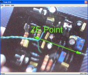
The thick grey wire is the signal.
The green/white is the zobel earth and the conections for the vbe.
I dont have groundloops or anything so thats no problem.
all transistors are isolated from heatsink but the heatsink is not grounded.
as powersuply i use 2* 33VDC and 15000µF
The thick grey wire is the signal.
The green/white is the zobel earth and the conections for the vbe.
I dont have groundloops or anything so thats no problem.
all transistors are isolated from heatsink but the heatsink is not grounded.
as powersuply i use 2* 33VDC and 15000µF
Have you checked all VBEs Inex?
Please, inform those VBEs voltages, please.
Also inform if you could measure some AC voltage in the output.... say...AC voltage that is not audio of course..with a short in the input.
Are those drivers hot?... install a small heatsinks on them if you feel them hot.
Is the zobel network hot?
Have you made vibrations in your board...knocking with your fingers or hitting the circuit with a pencil?....did it affect the noise?
Is this a hissing noise?
Are those noises popping?....cracking, scratching, humbling?
Also, can you please inform your heatsink dimensions...how many fins and fins dimensions too.
Do you know the exactly current you are using?...have you tweaked this current to plus and minus trying to obtain a better sound?
If you can... make recordings of the noise you have and send it as MP3 to my mail adress.
Well...i see that you have good knowledge...the solution to install a trimpot in series with a resistor, from base to emitter, into the VBE multiplier told me "a lot about yourself"...you have the knowledge of those practical tips and tricks.... do not be bothered with my questions.
I feel myself responsable related this amplifier..of course, as i made it to work fine i want to help folks to put it to work fine..every informations will be helpfull to our side...the cooperator's side.
Many obvious and idiotic question will be posted...for sure...but normally the errors we use to make are simple that way.
The idiotic questions posted do not means that we think you are idiot...but an idiotic error may be disturbing....all mistakes are idiotic..but the constructor is not....he is human and can make mistakes..but the damn error..this one deserve a hard title..ahahahha.
panzertoo@yahoo.com
regards,
Caros
Graham Maynard said:
rabbitz; any link to the LS you mention ?
Hi Graham
LS = loudspeaker? I'm not sure which one you are referring to so I'll cover the bases.
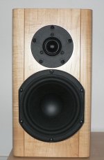
Here's a link to some I have built and the ones where Carlos was asking about the timber.
http://www.rzaudio.com/design.htm
The one I mentioned that I was building is the one in the pic and just finished today. It uses the Peerless DX25TG-05-04 and 830875 and has yet to be documented. The box is undersize for the mid woofer but perfect for it's intended application which is close to being near field.
There's nothing scientific about my cap waffle as it's purely observation only. In Australia it's hard to find good caps so was looking for some good well priced ones that I could buy from overseas. Nichicon fitted the bill and gave sonic benefits. Most of what I have learned about amps and supplies came from building my AKSA and Hugh's forum. I have less knowledge than Hugh has in his little toe.
That's interesting about running a smaller cap in parallel and will try that. I've seen it done in speaker crossovers and on output caps in a CD player where a small MKP is in parallel to an electrolytic.
Cheers
rabbitz
Attachments
Hi inex,
You do not have enough ground wires going to the pcb to be able to say that you don't have a ground loop.
Also a Zobel should be close to where it acts.
On the latest pcb it is between the output transistors.
I liked Nordic's description of his grounding; maybe if you copy that !
The thick copper ground track on the pcb near the input should be the point for all your signal and power related grounds, or you'll end up with some length of (single white) wire modulating the supply 0V line due to the loudspeaker current it is attempting to control.
Cheers ....... Graham.
Hehe, I did well?
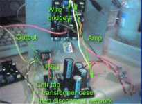
Ok here are phodies of the prototype monster.. wires will be trimmed etc when I know how big the case has to be and how close I can bring the transformers...)
My thinking in the wireing was to have the "noisiest" grounds closest to the ground entry point..., bypassing the PSU ground trace, so it can be left to do its job... make the electrons dance towards the amp...
Error--- where it says Trans case then disconnect networc... this is the wrong way around....
Sorry... little preoccupied, found out I must have surgery to remove wisdom teeth today...
Attachments
Thanks for the help.
But like i said the amp was working fine, exept for a few litle things.
so nothing to worry about
The noise is gone but the disortions with low bias are still there.
Did some new testing and shortened the input again, from C1 to in -
(instead of C1 to psu star ground oops sorry).
The ouput ac voltage is around 0V with my DMM and 5mV with my ac milivolt meter.
Bias
+ rail 134mA
- rail 131mA
Measured over a 0,1 Ohm resistor
My DMM is cheap so i dont know how accurate it is.
VBE
from ground to the emitter -1.10V
from ground to the collector +1.12V
from ground to base -0.49V
(DMM ground on Amp ground)
I'm going to rewire the amp now
zobel ground on amp board ground
speaker ground on psu ground.
amp board ground on psu ground
thats the right grounding method?
Hi inex,
you wrote >
I'm going to rewire the amp now
zobel ground on amp board ground
speaker ground on psu ground.
amp board ground on psu ground
thats the right grounding method?<
YES
NO
NO.
Your amplifier ground must be the ground for your LS and the PSU.
The input plus NFB ground on the PCB should be the zero reference point for all connected circuits.
Cheers ....... Graham.
inex said:I'm going to rewire the amp now
zobel ground on amp board ground
speaker ground on psu ground.
amp board ground on psu ground
thats the right grounding method?
Hi inex,
This is how I am wiring my DX Amplifier. I have done lots of amps like this in the pass without a problem. I'll let you know if there is a issue. Make sure your wires to psu ground are thick.
Graham's suggestion will work as well and may be better, but I doubt it will make an enormous difference. Have a look at Carlos's prototype's wiring. When I get around to updating the PCB I will try and incorporate Graham's suggestion by adding a few more earth connection points.
When you get a chance why not try a single external star earth and connect all earths to that. The current PCB is designed to allow that. If your external star earth is close to the PCB I think it will meet Graham's requirements.
regards
Greg Erskine said:.... I have done lots of amps like this in the pass
Lol, do we realy need to involve Nelson in this?
P.S. I got house wireing from the hardware shop for mine...so its the same stuff thats in the walls...
I am in no pain yet... surgery is scheduled for 1st of June...
I am allready out of my mind with anxiety... not to mention hateing the thought of anesthesia, being in a hospital gown with my balls hanging out, and my inhibitions plastered with drugs. I have no reaction to nails on a blackboard, but that cotton gause they use to stop bleeding/and for general dentistry make me want to vomit on contact...I used to feel the nails on blackboard thing when I was a kid, so I can compare it....not to mention dreading anymore pain... my back gives my enough pain as it is... the jewel I thought I hurt, was actualy just a referal pain from arthritis that moved into the bones in my groin area above the hipsockets...so now it hurts when I sit again... gonna be a colourfull winter I guess.
I am most certainly not my usual chirpy self tonight...will have to form some plan of action to deal with this...
- Status
- Not open for further replies.
- Home
- Amplifiers
- Solid State
- Destroyer x Amplifier...Dx amp...my amplifier