Hi!
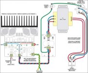
When it comes to amplifier grounding, this may be helpful. I know that is completely different amplifier, but i think the general principles of wiring, shown on that diagram are universal.
taken from: http://www.electoday.com/modules.php?name=Forums&file=viewtopic&t=5703
(btw: another interesting design)
regards
Attachments
Inex...i was thinking about your meaurements.
And i felt very strange with your results.
I would be happy to receive from you, informs about the VBEs of the output units, the upper and lower output units and the upper and lower drivers VBEs to see if a big unballance was there.
Your informs about voltages, i hope taken with digital voltimeter, are a little strange....you had a total of 2.22 volts...this is the voltage you could measure into the VBE multiplier..from Colector to Emitter.....and this will be divided into four base to emitter junctions...so... you gonna have 0.55V to each one if correctly distributed..... no distortions with this voltage, normally transistors do not distort in this operational point.
Of course...better will be 0.6V to each one of them.... so, measuring +1.20 volts at the colector and -1.20 volts at the emitter will be better...so...try to increase you bias to check your distortions....make the adjustment listening....but be carefull not to go too much into the adjustment.
Your 0.1 ohms resistance are too much small to protect your circuit...it is helping you to measure, but they are not protecting...as a short in the circuit will produce the full supply current entering and melting the board and parts.....the supply current will be feeding its maximum limit of current, and this can be 30 amperes of more, depending of the transformer.....and if this supply was extremelly ruge, some theoretical supply, that one could maintain 35 volts even during short circuits...you could have 350 Amperes into your board..the resistance is limiting absolutelly nothing.
Having 10 ohms, for instance, you would have a maximum of 3.5 amperes to each rail (with short circuits into entire circuit)... Also, the 100 miliamperes bias point could be achieved when measuring 1 Volt.
To obtain your readings of stand by current, you should measure 0.0134V (thirteen point 4 milivolts) that will be divided by the resistance of 0.1 ohms...this resulted in 0.134A (a hundred and thirty four miliamperes).... this small reading are extremelly unprecise in cheap multimeters.... also the 0.1 resistance use to be not precise too....0,8 to 1,2 ohms are not difficult to find on them..in special if they are different related brands.
Well.... something strange with those measurements...i hope you will find some error there, and this will explain why you have distortions....and those distortions seems a result of a underbiased amplifier, or extremelly unmatched transistors or enormous audio voltage entering the amplifier input.
I would like to know, also, the audio source you are using...how it is beeing excited by this audio...are your level too high?.... noise can come when you have an extremelly high level in the input...also extremelly high levels of hissing will enter the amplifier too.
I hope i could be helpfull to you.
Keep me informed as i need to know how this baby is related health.
Digital multimeters, with exausted batteries do not measure correctly.
Analogue multimeters use to not read correctly for hundred of reasons.
Your protective resistances must be substituted by bigger ones.
regards,
Carlos
Hi Nordic,
Stop being a girlie. I'm due to get my impacted wisdom tooth out as well, although I haven't a date yet. Bottom left? I've put mine off for 25 years, but a my last visit, the denist said now is the time.
Carlos has had teeth trouble as well, seems like it must have something to do with building DX Amplifiers.
hi ostry,
Very spooky. I'm building a SC480 at the moment with my nephew, for learning purposes. He's doing electronics at school. I also have another one built years ago. The earlier one wasn't wired up as per your schematic, but we'll do the new one as designed and compare the results. Either way, I can't imagine the earth wiring making enough difference to make these amps sound really good. The problem with these designs are they have to use generic components available from a small number of components suppliers. They are cheap though, I got mine for $12.50 an amp + $9.50 an PSU.
regards
Stop being a girlie.
I'm due to get my impacted wisdom tooth out as well, although I haven't a date yet. Bottom left? I've put mine off for 25 years, but a my last visit, the denist said now is the time.Carlos has had teeth trouble as well, seems like it must have something to do with building DX Amplifiers.
hi ostry,
Very spooky. I'm building a SC480 at the moment with my nephew, for learning purposes. He's doing electronics at school. I also have another one built years ago. The earlier one wasn't wired up as per your schematic, but we'll do the new one as designed and compare the results. Either way, I can't imagine the earth wiring making enough difference to make these amps sound really good. The problem with these designs are they have to use generic components available from a small number of components suppliers. They are cheap though, I got mine for $12.50 an amp + $9.50 an PSU.
regards
I have made all the dirtiest possible earth connections here.
And the amplifier continued to sound perfect...had not unstabilities, not noises.
I think that a good ground is a need...well..better is not to forget to ground the different stages that need grounding...the input transistor, the condenser at the second differential transistor base (with a resistance in series), the zobel and the output.
the major problems you may have are related to bigger errors compared with ground lines...in my personal point of view, it is very hard to produce ground loops using correctly designed boards.... as the one Greg has made...some, because of extremelly perfectionist character may think it is needed...i do not thing this is hardly needed.
Those distortions and noises found by Inex, are enormous in size compared to annoying effects caused by ground patches.
I do not think, and i did made testing on that, that ground can be so problematic....unless something was forget...i say...missed ground connection.
I will be much more happy if dear Ostry make an effort to show examples over the Dx board...showing the ground lines he thinks may be better this or that way....Ostry can paint collors and explain over the dx board offered in the forum and in the home page to do that.
To offer us other amplifier is very kind, but diverge attention related the amplifier in focus here.
Problems were found, by Inex, into the Dx amplifier,not the 480.
Ground schematics are extremelly important and usefull...also Klaas have already made us that offer, and we have Klaas board showing with clear colours, the wiring he made into the Dx amplifier...but much more important than that.... is to debug the amplifier, searching for major errors that can absolutelly kill the sonics..when ground patches disturb but do not kill the amplifier sonics in the same ammmount as errors make.
Yes...i turn a little bit excited.... or nervous, when i have someone with problems constructing the Dx amplifier...as it is so simple and easy.... this kill my future intentions to provide it as a Kit for my country, as i see that many problems happens during construction, and many of them need a very experienced constructors.
I could see that Klaas faced problems.... and more than once...also Nordic had small problems to adjust bias...he had to replace a resistance into the VBE multiplier....this is showing me that Kits may be very problematic as a future business, and that the follow up....the post sales will be extremelly time consumming.
I am a little frustrated..so...forgive if my words are too much direct...and if i am beeing not so nice as usual.
regards,
Carlos
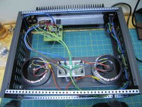
Mr. Greg Erskine have already one channel wired for testing purposes.
He gonna make board testing.... will check wiring in advance, ground patches and will be listening.
Soon...maybe in a matter of a week we gonna have his precious thougths about.
regards,
Carlos
He gonna make board testing.... will check wiring in advance, ground patches and will be listening.
Soon...maybe in a matter of a week we gonna have his precious thougths about.
regards,
Carlos
Attachments
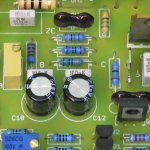
Carlos, that heatsink looks so small.. is it a low power version?
I think my heatsinks were big enough to just use one, at even the volume we use when we turn it up a bit, weekends...
Greg's PCBs work perfectly, and can be built with no worries...
If you do want to do a kit, you need a list of very fixed measureing points during building and setup sequence... and specify or include transformers...
P.S. tooth news... my dentist opted to do the job himself... and I am much more comfortable with someone who has 2 proper eyes... I just could not get a likeing in the other guy... apparently the eye is the result of a brain tumor, and he sees fine... but hey.
If it was only that I probably would not feel the way I do... I am super sensitive to people with bad juju... and this guy just activated every warning bell... which is too much combined with all the other factors I have to struggle against allready.
Nordic said:Carlos, that heatsink looks so small.. is it a low power version?
I think my heatsinks were big enough to just use one, at even the volume we use when we turn it up a bit, weekends...
Greg's PCBs work perfectly, and can be built with no worries...
If you do want to do a kit, you need a list of very fixed measureing points during building and setup sequence... and specify or include transformers...
Hi Nordic,
I hope the heatsink is big enough. I was under the impression that the DX AMplifier was a class AB amp. This is a 0.37c/W heatsink! I've used this heatsink for 2 channels on many 50w to 100w amps. All run cool to warm. I even have a 12w class A DOZ that runs very hot with 2 channels on it, but still it doesn't self destruct after many hours of playing.
http://www.conradheatsinks.com/products/single_f.html#MF30
What is the rating of the heatsink you are using?
I'm glad the PCB works, I was a bit nervous because I've never done one before.

I have an updated schematic that has the test values on it. Carlos and I have been doing it this week. I have not had a chance to uploaded it yet.
regards
Lol, its all good, I build exactly to the schematic and partslist from the site, only oversizeing the resitors on PSU with a few Watt for better thermal performance...
My heatsinks are 20 fins on 1cm thick, 200mm x 200mm, base, per channel... no idea what the rateing is... but the transistors run pretty cool... my GC's heatsinks run warmer under equal volume, and from same transformer...
My heatsinks are 20 fins on 1cm thick, 200mm x 200mm, base, per channel... no idea what the rateing is... but the transistors run pretty cool... my GC's heatsinks run warmer under equal volume, and from same transformer...
Re: Inex...i was thinking about your meaurements.
I'm an amp dummy, but isn't 10R required as the safety resistor so the bias can be set at 1V across the resistor? With 0R1 surely the bias would not be right if set at 1V.
I'm only thinking out aloud Carlos.
destroyer X said:
Your 0.1 ohms resistance are too much small to protect your circuit...it is helping you to measure, but they are not protecting...as a short in the circuit will produce the full supply current entering and melting the board and parts.....the supply current will be feeding its maximum limit of current, and this can be 30 amperes of more, depending of the transformer.....and if this supply was extremelly ruge, some theoretical supply, that one could maintain 35 volts even during short circuits...you could have 350 Amperes into your board..the resistance is limiting absolutelly nothing.
Having 10 ohms, for instance, you would have a maximum of 3.5 amperes to each rail (with short circuits into entire circuit)... Also, the 100 miliamperes bias point could be achieved when measuring 1 Volt.
I'm an amp dummy, but isn't 10R required as the safety resistor so the bias can be set at 1V across the resistor? With 0R1 surely the bias would not be right if set at 1V.
I'm only thinking out aloud Carlos.
Hey dear Nordic...do not complain..it is good to have it cold man!
Let's suppose that you will need them to work outside...some party or something alike....using different speakers..there are crazy monster speakers.... whose brand is "The drunkers", that goes 2 ohms in some frequencies...and sunligth touching the equipment... full volume punching the damn crazy drunker's speakers.......and during your audition, your wife...or worst...your wife's mother, install a little cloth over..ahahaha..to make it more pretty.
Then..you will be happy with your heatsinks...if you feel yourself disturbed with them cold..ahahahaha...install 2 resistors..22 ohms and 50 watts industrial units..one to each heatsink...make them touch the heatsinks...use thermal compound and attach them tigthly there...hehe..them you will have more 50 watts of heat to each channel to make you happy.
Aussie heatsinks are hipper super incredible huge heavy duty heatsinks... dampened with Kangaroo oil...cannot be compared with others...
ahahahahah!
regards,
Carlos
Hiii ... Carlos
Long Time No see
I look in thread and posting your DX 100
have a quick improvement
do still give schematic for free or
you start to sell this PCB ?
If you dont sell it maybe you can give me
for free
Just kidding, can you tell me how sweet the sound?
best regards
jeffry
Long Time No see
I look in thread and posting your DX 100
have a quick improvement
do still give schematic for free or
you start to sell this PCB ?
If you dont sell it maybe you can give me
for free
Just kidding, can you tell me how sweet the sound?
best regards
jeffry
All rigth Jeffry.... the sound is fine.. a very good sound amplifier.
respecting the limits we have when we have a simple, and cheap unit.
You can listen claps as claps...you will not listen claps as rain falling down into your roof.
Kisses will not sound as watter leakage.
The thunder sound will not seem to be a barrel hitted.
The sound of watter will not be alike rice shacking inside a metal can.
The voices will be present and clear.
Human voices will not be mixed...you can force our perception to separate them...and Dx amplifier will provide you the sonics that will allow you to listen A and B woman singing at same time...you will be able to listen them separatelly..focusing in one of them each time.
Saxophone and other musical instruments that have a piece of metal vibrating..will show you the clear scratching and annoying characteristics of the instrument played in front of you.
Bass punch will be strong and clear..the speaker will try to jump out from the metal chassis.
The amplifier will provide you very low level of hissing....noise are out of your music.
It distorts alike a crazy pig when over driven.....more than many other amplifiers...but...keeping the volume into reasonable levels you will not be annoyed....some people feel that distortion as "power"...many guys will be impressed..but they will be non audiophiles.
The amplifier has not that perfect treble Aksa 55 has....also has not that punch of dinamics Symassym can give you....also has not that incredible voices and bass quality that GEM can give you...but can save a lot of coins in your pocket ...beeing this, the main advantage.
Wanna the best possible option....to be sure you have the maximum possible quality in sonics...go to Aspens amplifiers and go directly, straigth and without doubts to Aksa55.....lifeforce will be even better if you like precision, low distortion sonics....all this is subjective..my opinion...others may think different.... off course they may say their amplifiers are better....hehe.
regards,
Carlos
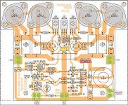
busy building a DX amplifier
Hi Guys....I am busy with my first DX amp. I used the PCB layout from the DX website and parts list. Wanted to switch the amp on last night but power went off in our area. Will give some feedback tommorrow if everything goes well.
Thanks Carlos for all your info. Can I use this amp as is with a +-47V DC transformer. The reason being I have a couple of these transformers and want to use them if I can. What modifications if any must be done to use this transformers with the DX amp? I am sure someone asked this before, but do not have the time to read the whole discussion of this amp. Can you help me please Carlos?
Thanks
macd
Macd...welcome to the Dx thread...push your seat and have a drink with us.
Your transformer will need 250 watts each one of them....as you will have 170 watts of peak power.... and this is undistorted power over 4 ohms.
So..using normal standard impedances.... 6 to 8 ohms, you will have more than 80 watts rms undistorted.
Using 4 ohms, your maximum output can reach 26 volts undistorted..your current willl be something around 2.6 amperes to each rail.
Your Vr1, the offset adjustment trimpot will be adjusted around 7700 ohms to first set up moments.
Your gain adjustment resistor will be 1K6 or 1K8 (R10)
All condenser will need to work into your supply voltage..so..at least 50 volts insulating voltage condensers will be needed, better to use 63 or 70 volts units.,
The bootstrap condenser, this one will be a 100 volts unit (minimum).
To the input, 2n5401
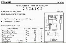
To the voltage amplifier position use 2SC4793
To the drivers position use 2SC4793 and 2SA1837
To the output, use two pairs of 2sc5200 and it's complementary..each one of them using 0.22 ohms resistor into the emitters.... 5 to 10 watts resistance.
Output fuses may be 3.5 amps to 8 ohms and 6 amps to 4 ohms (as the transformer will loose some volts and power will not reach the maximum possible continuously)
Supply electrolitic condensers, from 10000 to 15000 uf each rail will be good enougth. to each amplifier... this little monster may use all the condenser charge to reach your 160 to 170 watts undistorted during short time peaks...and much more power distorted.
Heatsink must be really big...show me the ones you will use in advance of your construction please.
I thank you by the preference.
" Dx amplifier team, Greg, Carlos, Klaas, Nordic, Inex, Phong, Ostry, Stuey and many other that are doing, and many others keeping their works in secret welcome you "
My brazilian friends, Polín, Egberto, Luiz and Fernando, the ones are listening my own Dx constructions , are giving you their welcome too.
Uops!..i forget to suggest you 160 miliamps of stand by current...but as a reference only...you must tweat to obtain the better point of bias listening to a very low volume music....optimizing this you will have better sonics and lower heat.
regards,
Carlos
Your transformer will need 250 watts each one of them....as you will have 170 watts of peak power.... and this is undistorted power over 4 ohms.
So..using normal standard impedances.... 6 to 8 ohms, you will have more than 80 watts rms undistorted.
Using 4 ohms, your maximum output can reach 26 volts undistorted..your current willl be something around 2.6 amperes to each rail.
Your Vr1, the offset adjustment trimpot will be adjusted around 7700 ohms to first set up moments.
Your gain adjustment resistor will be 1K6 or 1K8 (R10)
All condenser will need to work into your supply voltage..so..at least 50 volts insulating voltage condensers will be needed, better to use 63 or 70 volts units.,
The bootstrap condenser, this one will be a 100 volts unit (minimum).
To the input, 2n5401
To the voltage amplifier position use 2SC4793
To the drivers position use 2SC4793 and 2SA1837
To the output, use two pairs of 2sc5200 and it's complementary..each one of them using 0.22 ohms resistor into the emitters.... 5 to 10 watts resistance.
Output fuses may be 3.5 amps to 8 ohms and 6 amps to 4 ohms (as the transformer will loose some volts and power will not reach the maximum possible continuously)
Supply electrolitic condensers, from 10000 to 15000 uf each rail will be good enougth. to each amplifier... this little monster may use all the condenser charge to reach your 160 to 170 watts undistorted during short time peaks...and much more power distorted.
Heatsink must be really big...show me the ones you will use in advance of your construction please.
I thank you by the preference.
" Dx amplifier team, Greg, Carlos, Klaas, Nordic, Inex, Phong, Ostry, Stuey and many other that are doing, and many others keeping their works in secret welcome you "
My brazilian friends, Polín, Egberto, Luiz and Fernando, the ones are listening my own Dx constructions , are giving you their welcome too.
Uops!..i forget to suggest you 160 miliamps of stand by current...but as a reference only...you must tweat to obtain the better point of bias listening to a very low volume music....optimizing this you will have better sonics and lower heat.
regards,
Carlos
Attachments
Welcome Mac hope you enjoy the amp...
I am floating, doc shot me up with morphine 10 minutes ago as I was in a bad way... now it seems kind of funney
ALso got my first glasses today... omg I was actualy blind it seems... I was so embarrased when I put it on, the girl seemed so close, it felt like I was in her personal space... I will have to practice wearing em around my wife first... feels like the coolest binoculars eva!!!!!!!!!
Re: Inex...i was thinking about your meaurements.
I'm a litle tired now but i will try remeasure the amplifier and recheck the resistors for the right value.
My heatsink is pretty small (related to youre views) but it isnt getting hot at moderate music level (easy to touch).
The tempeture of the drivers are below that of the heatsink.
the Zobel isnt hot when i touch is but it could be broken, the resistor is a 0,25W type same as r12 and r13.
About the audio source, i used a PC or a car radio, i dont know the voltage but i will measure that to.
If the gain of the vas is to low the audio source must be louder and that would ad disortions?
When have some time left i will replace the drivers and Vas to see if it has effect.
Tommorow i will measure the amp with an oscilioscoop (if i havent blow it up before )
)
destroyer X said:
And i felt very strange with your results.
I would be happy to receive from you, informs about the VBEs of the output units, the upper and lower output units and the upper and lower drivers VBEs to see if a big unballance was there.
Your informs about voltages, i hope taken with digital voltimeter, are a little strange....you had a total of 2.22 volts...this is the voltage you could measure into the VBE multiplier..from Colector to Emitter.....and this will be divided into four base to emitter junctions...so... you gonna have 0.55V to each one if correctly distributed..... no distortions with this voltage, normally transistors do not distort in this operational point.
Of course...better will be 0.6V to each one of them.... so, measuring +1.20 volts at the colector and -1.20 volts at the emitter will be better...so...try to increase you bias to check your distortions....make the adjustment listening....but be carefull not to go too much into the adjustment.
Your 0.1 ohms resistance are too much small to protect your circuit...it is helping you to measure, but they are not protecting...as a short in the circuit will produce the full supply current entering and melting the board and parts.....the supply current will be feeding its maximum limit of current, and this can be 30 amperes of more, depending of the transformer.....and if this supply was extremelly ruge, some theoretical supply, that one could maintain 35 volts even during short circuits...you could have 350 Amperes into your board..the resistance is limiting absolutelly nothing.
Having 10 ohms, for instance, you would have a maximum of 3.5 amperes to each rail (with short circuits into entire circuit)... Also, the 100 miliamperes bias point could be achieved when measuring 1 Volt.
To obtain your readings of stand by current, you should measure 0.0134V (thirteen point 4 milivolts) that will be divided by the resistance of 0.1 ohms...this resulted in 0.134A (a hundred and thirty four miliamperes).... this small reading are extremelly unprecise in cheap multimeters.... also the 0.1 resistance use to be not precise too....0,8 to 1,2 ohms are not difficult to find on them..in special if they are different related brands.
Well.... something strange with those measurements...i hope you will find some error there, and this will explain why you have distortions....and those distortions seems a result of a underbiased amplifier, or extremelly unmatched transistors or enormous audio voltage entering the amplifier input.
I would like to know, also, the audio source you are using...how it is beeing excited by this audio...are your level too high?.... noise can come when you have an extremelly high level in the input...also extremelly high levels of hissing will enter the amplifier too.
I hope i could be helpfull to you.
Keep me informed as i need to know how this baby is related health.
Digital multimeters, with exausted batteries do not measure correctly.
Analogue multimeters use to not read correctly for hundred of reasons.
Your protective resistances must be substituted by bigger ones.
regards,
Carlos
I'm a litle tired now but i will try remeasure the amplifier and recheck the resistors for the right value.
My heatsink is pretty small (related to youre views) but it isnt getting hot at moderate music level (easy to touch).
The tempeture of the drivers are below that of the heatsink.
the Zobel isnt hot when i touch is but it could be broken, the resistor is a 0,25W type same as r12 and r13.
About the audio source, i used a PC or a car radio, i dont know the voltage but i will measure that to.
If the gain of the vas is to low the audio source must be louder and that would ad disortions?
When have some time left i will replace the drivers and Vas to see if it has effect.
Tommorow i will measure the amp with an oscilioscoop (if i havent blow it up before
)- Status
- Not open for further replies.
- Home
- Amplifiers
- Solid State
- Destroyer x Amplifier...Dx amp...my amplifier