Parfait!..you got it Gaetan!
If emitter resistance are a need...people would ask constructors to use long spealer cable to contribute with more series resistances.
If we use to reduce those cable resistances, is because resistances there are not good.
Good Gaetan.... thanks....short and perfect argument.
BTW: using more than one pair or transistors into the output, those emitters resistances will be extremelly needed to equalize the current. Not having them, he higher gain unit will hold the biggest part of the job.... may overheat and burn.
regards,
Carlos
Re: No...absolutelly not!.... the need of resistors into emitters are to equalize gain
Hi Carlos
I agree that it can be confusing for beginer, but I wont blame anybody, I presume that most just want to help.
I do electronics since years but I don't have a good knowledge in design and in schematic analysis. I don't have any courses in electronics, I did learned by myself.
Btw, here's a little "confused guy" question..") Is the schematic in your Dx amp web page are the final one or you did few changes or tweak since ?
Is the schematic in your Dx amp web page are the final one or you did few changes or tweak since ?
Thank
Gaetan
destroyer X said:...
.........................................................................................................
Dear Sixtek
As i told you in the forum thread and directly by typed mail and audio mail.
You see the confusion...each small thing alike that generates confusion to a lot of guys.
Every thread needs to have a single mouth.... and in this case, the mouth is the home page...the schematic posted is the Official informer...and there...no resistances into the emitter.
If we go tweaking, the amplifier will be never ready...many friends, because of that, install their "to do" machines into the "stand by mode"...and they keep this way waiting the amplifier to be really ready.
Modifications, related the schematic are closed!
Everyone has the rigth to construct or not to construct...also to make their modifications under their own risk...modifications will not be accepted by Mr Schematic...even asking him he will not answer..as schematic do not talks..ahahahha!
regards,
Carlos
Hi Carlos
I agree that it can be confusing for beginer, but I wont blame anybody, I presume that most just want to help.
I do electronics since years but I don't have a good knowledge in design and in schematic analysis. I don't have any courses in electronics, I did learned by myself.
Btw, here's a little "confused guy" question..
Is the schematic in your Dx amp web page are the final one or you did few changes or tweak since ?Thank
Gaetan
Yes Gaetan, that schematic is the last and final one.
But, as you could see, the bias control shown there, has VR2 and R14 as bias control.
The "standard" to amplifier VBE multiplier was provided as i have perceived that some guys would use not so big heatsinks as needed not to use some thermal compensation.... and this circuit is a possible option to substitute VR2 and R14.
Also, there are the diodes option, also controls temperature.
The VBE multiplier, even not included into the main schematic, is something suggested to those ones do not feel themselves very safe related audio electronics..in other words...to non experienced guys.
What is non experienced guys...the ones never constructed discrete amplifiers.also the ones never had faced problems during construction, so...they do not know that humans do a lot of inversions and mistakes....non experienced guys turns paralised when face problems...experienced guys know how to measure and to debug the amplifier...normally bugs are construction errors.
You can see that VBE multiplier, in an external board, posted many times in this thread..also, of course, you have informs of it into the home page.
I strongly suggest you, my friend, to be patient and to read this Dx amplifier thread since the early begining, as many others informations are there and i will repeat things already posted and already discussed in details...of course i can do it..but it is a little non sense having those details posted.
As i could learn, doing that thread, there are hundreds of doubts that people may have...and the major part of them already have beeing discussed.
You are invited to read....if do not want...of course i will be helping you anyway.
Yes..those guys are cooperating having good will..but even having good will, are out of philosophic lines we follow in the thread....Iran is also cooperating with Iraq..do you agree?...is this what we want?
You was the one had immediatelly doubts...what to follow?...the Dx thread or the one told emitter resistances were missed?
regards,
Carlos
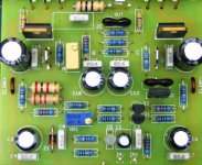
Inex, please, send me your board image using full resolution of your camera.
That good image you made...but with more pixels and more ligth, so i will be able to help you searching for possible errors.
Please, send them directly to my mail adress.... maximum possible quality please.
panzertoo@yahoo.com
If possible, produce atop view alike the one i am showing you, this way focus distance, from lenses to board will be the same in all directions...this will make focus crisp.
If possible, use the focus in manual, or move your camera 1 centimeter up after focusing, because some cameras will focus the board and not the components...first auto focus, them try to move camera upwards.
An image of the copper lines can be great too...under the board images are helpfull too...but i will succeed to observe depending of the image quality...and for this board size....4 Megapixels is not too much data. (0ur eyes, to visual inspections, have something that could be compared with 500 Megapixels)
I would be happy to receive ALL your transistors VBEs to help you to conclude were is the problem.
regards,
Carlos
Attachments
Hi Carlos,
Sixtek asked about bias and emitter resistors. Also Gaeten about emitter resistors.
I remember reducing class-AB bias in the past and the reproduction sounded 'thin' as a result.
There was no explanation for this on a scope, nor via simulation as I checked just now.
I have just added emitter resistors to your simulation circuit and found this increases the sine distortion.
I know you have taken care to audition with and without emitter resistors and came down with a deliberate choice to NOT use them.
Simulation suggests this was a good choice.
Regarding bias. The changes in simulated performance beyond a minimum level are not great, and under many circumstances (depending on the transistors used) might not even be detectable.
However, I am sure you had in mind the variation in output stage temperature, between light and loud duties. This would mean that too low a bias cannot be set for fear of it becoming inadequate under some circumstances, and thus the Dx not always performing as expected.
So whilst it might be possible to obtain lowest "distortion" with say a 10 to 15mA setting, it could not be guaranteed that an output stage would track that current under all circumstances. However running at a higher quiescent current is likely to cover a greater tracking range of cold/hot variation, as I am sure you intended anyway.
Cheers ....... Graham.
Hi Sixtek
Feel free to e-mail me.
I think the point that Carlos has made is that he has already checked points you mention, and the decisions related to this simple and repeatable DIY project have already been made.
I don't doubt that any experienced designer could improve this circuit further, but would it still be as straightforward for everyone to use afterwards? Construction errors can be puzzling enough for any of us, but to have oscillation or bad bias drift after it has been constructed differently is hardly anything that Carlos could be expected to stand over, as he has so freely done thus far.
Cheers ........ Graham.
No exactly Sixtek..something must be said..and Graham is the main co-designer
He is one of the responsables of this amplifier.
Was good to mention this Graham...i hope the "theorist figther groups" do not follow you...ahahahhahaha
Because of that, i have set, as standard, a current from 50 to 100 miliamperes...this will turn clear that.
It is variable, will depend from the transistors used.
That i may need to be tweaked to find the audible better point.
Also that it is possible, that something out of that margin will work too.
A flexible amplifier, simple, not high tech, easy to construct, can use junk transistors, cheap and producing nice sonics that will not be ashamed for any other one...can loose to others..but difference will be small and will not justify the increasings in cost to produce a sligtly better one.
Beeing flexible the choice of parts..of course i have created problems to myself, as bias will be critical to some parts and people will need a reasonable knowledge to compensate things.
I am starting agreements with Greg, and in advance, explaining to you dear Graham, that i want to revert this freedom of choice..asking, stimulating, advising, suggesting people to use the standard, low cost, transistors posted into the home page..
But i want to listen you and Greg in advance.
go directly to my mail please, dear Graham.
regards,
Carlos
Just to clear up any possible confusion about bias-setting, i completed the experiment of setting bias using the scope.
At 11 mA the wobble indicating crossover-distortion disappears.
Upping the bias in 10 mA increments till i reached 100 mA didn't decrease performance, the wobble didn't re-appear.
So 50 mA is indeed a valid choice to add some margin in case of bias-drift/ variations due to parts used.
Best regards,
Klaas
Hi Graham and Carlos
You said very interesting advices about about emitter resistors and sonic quality of a power amp, things that are not in books, if you have others advices like that to say about things to know for best sonic quality of a power amp, can you open a subjet for that in the forum ?
Thank
Gaetan
You said very interesting advices about about emitter resistors and sonic quality of a power amp, things that are not in books, if you have others advices like that to say about things to know for best sonic quality of a power amp, can you open a subjet for that in the forum ?
Thank
Gaetan
Graham Maynard said:Hi Carlos,
...
I have just added emitter resistors to your simulation circuit and found this increases the sine distortion.
I know you have taken care to audition with and without emitter resistors and came down with a deliberate choice to NOT use them.
Simulation suggests this was a good choice.
...
Cheers ....... Graham.
Hi
You and others talk about simulation, is it a software that you use, what software it is ?
Is there a freeware who do the same work ?
I have a Pc Pentium and Win XP
Thank
Gaetan
I can try to upload the TINA simulator...it is great, but a forum friend..heheh....
....someone very close to us...very, very near us....also in this thread can do better job uploading to you in such a way you will use four diskettes.
Tina will work with Windows 98 and up..also Mileniun...and Pentium bigger than 100 Megahertz will work with it.
I have also the Multisim 2001..this one is hard...it is hardly protected and it is very big too.
I have the Tina files mixed with Velox, hi speed Internet Conexion Software from Telemar...the biggest telephone system here..one of the four biggest here...it is a mess there, say, in the files mixed... and i do not know Gaetan, what is Tina files and what is Velox files...
If this secret guy did not move....i will try to upload you the entire material.
Gimme...give me your adress dear Gaetan...E mail adress..having one Yahoo adress will be better, as i can send bigger files than 10 Megabytes using Yahoo...... say...from Yahoo to Yahoo.
Related to tips and tricks.... really, i will have first have to discover ,what i know that people do not know....and then, organize that material to publish...problem is the "theorics, Hiper Enginners Tatic Strategic Figther Group"..they will invade to ask how i have measured that electron spining that way..also why it is not spinning the opposite..if i have sure they spin.
My experience is using ears...they use eyes on instruments...a problem to me to post those things...but i have courage enougth....and i will do it in the future...will post and them i will run out from there, leaving room to them figth till be tired..i will unsubscribe as i already know them very well..and will let to some moderator the damn work to finish with the probable mess that crazy thread will end...ahahahahah!
We have fair Weldon..... Pink fast trigger..... SY desintegrator...Planet10 the aliens hunter or frugalfirer.... Variac the Evil melter and others too...will not tell their nick names now..as they may react...and better not to have ALL them against you.....less than half of them will be more than enougth.
This thread,this one, has already many informs...the reasons of remotion of this, of that, of those...why this and that.... take some time Gaetan...and please, come to visit the whole thread.
We will be honored with your presence...be sure about that..each good candidate to construct is the "frite potatoes king" in this place. (and when i realise that the guy will not construct..the guy will turn half part of nothing..result will be divided by 1000.....kidding...not so much, of course!)
regards,
Carlos
Attachments
gaetan8888 said:
You and others talk about simulation, is it a software that you use, what software it is ?
Is there a freeware who do the same work ?
Many of us use LTSpice (aka. SwitcherCAD) which is freeware:
http://www.linear.com/designtools/software/switchercad.jsp
Hey, John Curl just told us in another thread that even Walt Jung uses LTSpice (well, he is retired from AD now, of course
).Note that Spice is the basic kernel and standard and then there are a lot of implementations of it, both free and commercial, such as LTSpice, PSpice etc.
The bear made a triangle...as returned to the same point.
What colour had that bear?..hummmm.
My last neuronium is cooking...
Eva is good to discover those things.
I am trying Christer....the problem may be a colour, that
has a name, that remembers the word triangle i thing..
But i do not know colours in English...only basic ones.
Good Christer...very good.
I will provide one to you soon.
regards,
Carlos
Oh pain!..what an Envy!.. I am green with envy!
Klaas, my dear pioneer constructor, found in a metal junk yard, an entire Akai amplifier from the eigthies...with transformer, heatsinks and a lot of things.
My God!..... price was lower than 10 dollares!.
I am not lucky this way.... things to enter here are always hard.. i have to clean my bank account to buy those things.
" Dx amplifier can be constructed using Junk heatsinks, junk resistances, junk transformers, junk chassis"
Grrrrrr!....... aaagh!....grumpf!
Envy!!!!
regards,
Carlos
.....................................................................................................
Intelligence test will be removed soon...answers here, if allowed, or direct to my E mail adress provided in the forum data.
......................................................................................................
Attachments
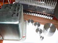
Yes, it was a nice find , parts would be nice for a "whimpy" version of DX-amp.
Transformer is about 150 va, dual 25 volt ac secondaries.
Heatsink is, using Carlos' calculation, good for dissipation of about 100 watts.
The copper bars in the picture were included, they're 60mm2.
Reason i like these things is, they show you don't have to break the bank to build nice stuff, if you're patient and lucky.
Related your riddle, Carlos, you have mail
Best regards,
Klaas
- Status
- Not open for further replies.
- Home
- Amplifiers
- Solid State
- Destroyer x Amplifier...Dx amp...my amplifier