But, that's just my opinion and also O.T. What is your point of view on your own question?
Judging by your answer, you had not twigged my point. Admittedly this isn't much discussed and could spawn a whole thread...
I asked the question because you seemed to be making a qualitative difference between speaker distortions and amplifier distortions and saying that while the figure for speaker distortion is higher (several orders of magnitude higher when we're speaking of amps with THD measured in single digits ppm or below) its quite different from amp distortion.
For myself, I'm not at all convinced that making such a distinction is valid for all distortions in the system, which is why I mentioned the kind of distortion which results from the interaction of the amp's finite output impedance with the non-linear electrical properties of the speaker. I do agree with acoustic distortion being different from electronic distortion, and concur its far more benign. But there is this third category which we could call 'electro-acoustic' distortion which seems by and large to be neglected.
It (electro-acoustic distortion, for want of a better term) only appears in the electrical output of the amp when a speaker is connected - its not there when the amp drives a pure resistor load. So if the amp's distortion is measured only into a resistor, we won't know how well it will do into a real-world load distortion-wise. The distortion comes about because the magnetic circuit of the speaker's voice coil is not linear - there are parameters which vary with the voice coil's displacement from rest position - the major one of them being inductance (in my understanding, I'm not a drive unit designer).
So when driving a real-world speaker, the amp sees an inductance which varies over one cycle of the driving waveform - in conjunction with the amp's own output impedance this forms a potential divider and therefore the attenuation varies over the course of a single cycle. The result therefore is distortion of the voltage waveform at the voice coil.
Does that help make any of my point clearer?🙂
What I'm not saying here is that electro-acoustic distortion is anything to worry about. But to my mind it does mean that ultra-low distortion amps are an interesting academic exercise only unless they achieve that ultra-low distortion into a real-world load. Even then I doubt that they're really going to be useful towards the goal of better sound quality. But I see that Edmond's motivation is the challenge rather than the sound and I do agree, the intellectual challenge is worthy.😀
Hi abraxalito,
Well, we both agree on the issues regarding amplifier / load interactions. But there are so many variables that it can't be something open and shut in this thread. Even as a topic on it's own, the lack of an accepted universal model of a load really hinders the discussion. Some models have been suggested here and there, but nothing ever came of these. No industry agreement. However, just you watch. As soon as a standard load with reactance is specified, the first amp tests will perform at an average level. The next model year will see a crop of product designed to measure well on that standard load.
As for the resistive loads we currently use (both 8R0 and 4R0 in my case), I don;t see a problem. The standard load exists in order to allow every manufacturer to publish specifications on a semi-equal playing field. Ofcourse we also see some manufacturers making up their own tests and terms. Even audio reviewers feel competent enough to create terms and tests. It's human nature with some of us to cheat to get ahead.
Since we are in the topic of ultra low distortion figures, I think they can be valid. An amplifier that has been designed and built with really low distortion stands a much better chance of sounding very lifelike than one whose distortion has been allowed to be much higher than average. Attaining this low distortion means that most distortion mechanisms have been tamed or eliminated. A good start. As you know, this isn't carved in stone, so we have amplifiers that measure very well but sounds badly. The reverse can also be true.
I'm pretty sure that the interactions between amplifier and load have been discussed somewhere around here. I think I saw a thread dedicated to that issue anyway.
Let's now return to the original topic for this thread.
-Chris
By losing 10dB NFB will it do well still? How many Volt on 8R it can do now? 10 or 18? I see some specs in the pdf but I don't know German. Yes, if it can do over 50W with first 10W class A decently and being DC, why not, send. I have a friend with 20W tubes that needs double and more for his 88dB speakers but will cost much weight and expense to go 60W. Maybe he can try something logical SS and decide.
Losing 10db of GNFB doesn t hurt the perfs, but 10W in classA from
a 20W amp is not the same as 10W classA from a 50W amp..
Since the iddle current must be the same, the latter one will
have way more thermal dissipation, ruining the whole idea
of economical class A...
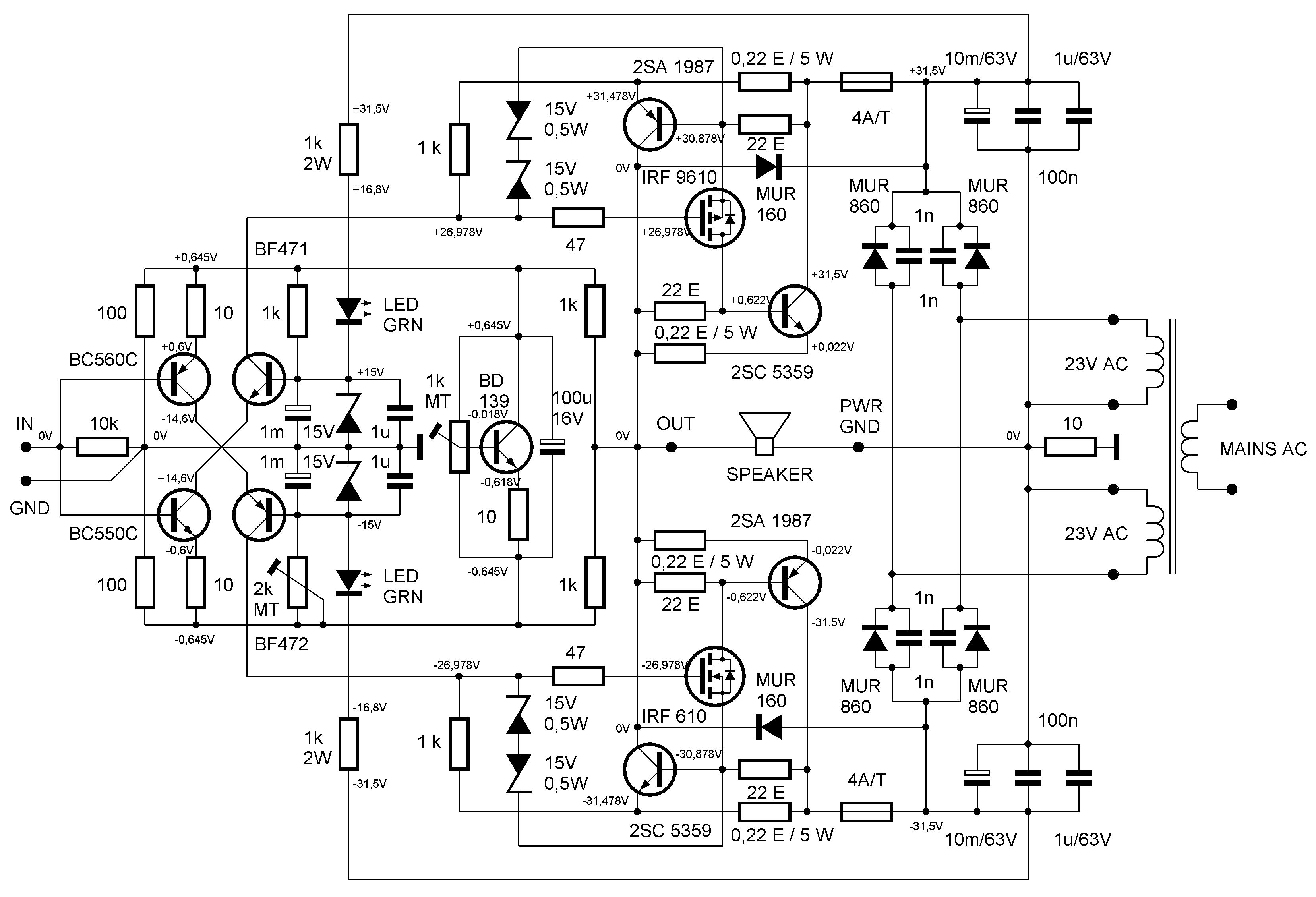
Anyway, here two versions which can deliver about 45W/8R..
You will notice that going output DC coupled increase complexity
by a wide margin..
And the schematic doesn t include the mandatory DC output protection.
Myself, i use a symetrical differential that is relatively high
THD but display a Tube like harmonic content.
I will make a thread about this one in some times..
Attachments
Hi Wahab,
your findings were extraordinary for me,
could you add some more amps to your sims, like SYMEF and SSA end reheat this excellent thread?
http://www.diyaudio.com/forums/solid-state/198500-symef-amplifier-17.html#post2886765
http://www.diyaudio.com/forums/atta...fier-ssa-20bigbt-20basic-201_1-20voltages.jpg
Hi , Padamiecki
Both schematics have issues.
The Symef is not stable and should be re designed i think ,
while this version of Lazycat s amp is marginally stable only ,
with quiescent current highly variable with temperature.
Also THD is relatively high.
I will post later some pics after further sims..
Both schematics have issues.
The Symef is not stable and should be re designed i think ,
while this version of Lazycat s amp is marginally stable only ,
with quiescent current highly variable with temperature.
Also THD is relatively high.
I will post later some pics after further sims..
Amp Not coming ON
Hi, I have a Kenwood Recevier, V6010, it goes into stand by mode when switched ON....i was told that the ICs STK 410-030D, STK 411-230D and CPX 82832-155Q were faulty...
Can the CPX 82832-155Q too cause this problem( this is for in/output selection) ???
Kindly advise....
Thank you..
Hi, I have a Kenwood Recevier, V6010, it goes into stand by mode when switched ON....i was told that the ICs STK 410-030D, STK 411-230D and CPX 82832-155Q were faulty...
Can the CPX 82832-155Q too cause this problem( this is for in/output selection) ???
Kindly advise....
Thank you..
- Status
- Not open for further replies.