Hello All...
6-24 is built and running nicely. The xo point is at 80 or so Hz (c=.1 uf c/2= .047uf / 10k in series with 50k pots).
I am running stereo 12" subs driven by a PAIR of Hafler XL 280 amps in bridged mode (300ish watts 25k input impedance)
My only concern is that it seems I have to drIve the LP output pretty hard (full throttle on LP with HP feathered in as well as pumping the preamp up a bit) with this setup.
I also have a Paradigm servo-15 (400ish watt class D 50k input impedace) that the 6-24 appears to drive with ease to get similar volume levels ( quarter or a bit more turn of LP input to match full volume of the HP). Again also available is an opamp based sub x-over (Paradigm X-30 output imp ?) that drives the the Hafler bridged setup with only slightly more effort (1/4 more turn on output) compared to the servo15.
I'm guessing that some impedance mismatch or capacitive roll-off trickery is plaguing me here. Hopefully one of you Gurus can offer a suggestion towards matching the low pass section of my system a bit better.
Thank You....
Side note.... I always thought the Opamp based cross was pretty decent sounding UNTILL the 6-24 was put in place with the AlephJ...wow....Clarity!!!
As usual I'm confused. Specifically over the calculation over the "C" cap value. In the write-up it says this…
For 6 dB/octave example, the formula for C is C = 6000 / Freq". Further down it says this...
18 dB/octave Filters. Once again, we see that the formula for the stock values of the capacitors is very similar, approximately: C = 7000 / Freq"
Why is one computed with 6000/Freq and one 7000/freq?
For 6 dB/octave example, the formula for C is C = 6000 / Freq". Further down it says this...
18 dB/octave Filters. Once again, we see that the formula for the stock values of the capacitors is very similar, approximately: C = 7000 / Freq"
Why is one computed with 6000/Freq and one 7000/freq?
Why is one computed with 6000/Freq and one 7000/freq?
The smartass answer is "because the math"
")
My guess is that those numbers are useful approximations for the benefit of the average DIY builder. They may have been arrived at by trial and error with the finished circuit or by messing with the math or a simulation.
If you're interested in the topic in depth I'm sure there are web sites that can help. I have the book "Active-Filter Cookbook" by Don Lancaster. I remember him from the hobbyist electronics magazines in the 1960s. He's a good explainer and in this book he includes the circuits, the theory and the math, along with practical advice.
From the PDF 6dB or 12dB filters use frequency divided by 6000. For 18dB and 24dB use frequency divided by 7000.
For 12dB C = C/2 Each position of the jumpers adds components (caps and resistors) to the circuit as the slope increases and that is what I think causes the math to change.
For 12dB C = C/2 Each position of the jumpers adds components (caps and resistors) to the circuit as the slope increases and that is what I think causes the math to change.
Let me try again... under what circumstances is the math correct to use 6000 and under what circumstances is it correct to use 7000. Do you use one on the high pass and the other on the low pass?
You use the same values for C and C/2 everywhere in the circuit. You calculate the value of C using the formula for the degree of filter you want to build (although the same value works for more that one type).
EDIT: Signal lost beat me to it thanks
Last edited:
From the PDF 6dB or 12dB filters use frequency divided by 6000. For 18dB and 24dB use frequency divided by 7000.
For 12dB C = C/2 Each position of the jumpers adds components (caps and resistors) to the circuit as the slope increases and that is what I think causes the math to change.
That's what I needed. Thanks! That wasn't clear to me in the PDF.
So if I want a 3K crossover center with a 24db slope... C=6000/3000 or 2nf for C and 1nf for C2. Is that correct?
That's what I needed. Thanks! That wasn't clear to me in the PDF.
So if I want a 3K crossover center with a 24db slope... C=6000/3000 or 2nf for C and 1nf for C2. Is that correct?
Sounds right. On Digikey the recommended capacitor brand is sold in pf so you would want as close as you can get to 2000pf and 1000pf.
Thanks! I did get that decoder ring.
Is this the correct series Cap? FKP2C016801D00HC00 WIMA | Mouser
Is this the correct series Cap? FKP2C016801D00HC00 WIMA | Mouser
It depends on what kind of slopes you are going for. If you want a low crossover frequency, you can go for larger values. I have ordered:
R79IC2470DQ40H KEMET | Mouser Sverige
R79IC3100DQ40H KEMET | Mouser Sverige
R79IC2470DQ40H KEMET | Mouser Sverige
R79IC3100DQ40H KEMET | Mouser Sverige
Thanks! I did get that decoder ring.
Is this the correct series Cap? FKP2C016801D00HC00 WIMA | Mouser
That's the type recommended in the parts list and the dimensions look about right. It's nice to at least get the same lead spacing as the circuit board plus a body size that fits in the space.
Yes I saw I did that. Thanks for letting me know though!
I did receive the parts kit today. I have one F5 but also got parts to build a second F5 to use after the crossover. I'll use my Korg B1 as the preamp. Still deciding what speaker to build to use with this signal/amplification chain. Until I do that, I really won't know where I want the frequencies to be centered. But I could build everything and add in the C and C2 caps later. That may even be a better plan as I can run a DATS scan on the speakers and confirm the TS parameters before securing the adjustment range I want. This project should keep me busy for a while...
I did receive the parts kit today. I have one F5 but also got parts to build a second F5 to use after the crossover. I'll use my Korg B1 as the preamp. Still deciding what speaker to build to use with this signal/amplification chain. Until I do that, I really won't know where I want the frequencies to be centered. But I could build everything and add in the C and C2 caps later. That may even be a better plan as I can run a DATS scan on the speakers and confirm the TS parameters before securing the adjustment range I want. This project should keep me busy for a while...
Last edited:
I jumped on the kit when it was first available but had no speaker for it. So I used some Jamo drivers purchased from PE over ten years ago. Set up a 12dB with 3.3 caps for about 1800h
Totally exceeded my expectations. I messed around with the filters (per Nelson's instructions) and built a second kit with a higher crossover point. Built two more pair of speakers to play with and learned alot. finally set up a 24db at 2121 hz and that has been wonderful.
So my advice is to start somewhere and then fiddle about. If you are going to make the crossover point high you may want to swap some 4.7K resistors for the 10k ones to give you more adjustment range on the high pass section. Some of my pots are near their minimum setting to get the values I needed.
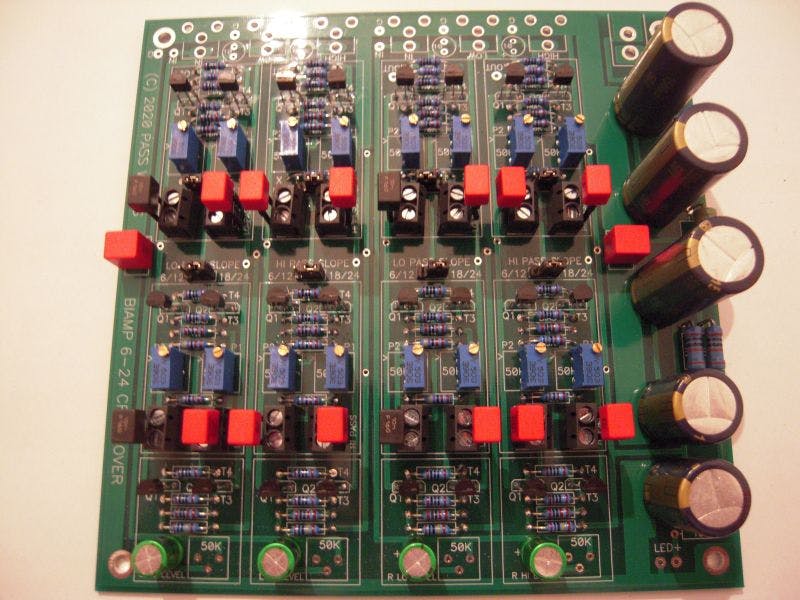
That seems like a good suggestion. I an really more of a speaker builder than an electronics wizard. As you can probably tell from my basic questions. So this electronics build is more about a speaker experiment than an electronics education. I have a lot invested in the speaker construction including a CNC router, lamination/veneering capabilities, etc. So I'm going to work on the speaker design first instead of having the tail wag the dog. At least in my case. But I did notice this picture on the Kits page showing someone using terminals to mount the C caps. That would make it very easy to change them as I work with things if they get out of range.
An externally hosted image should be here but it was not working when we last tested it.
Can you post a suggested part number just to give us an idea of what multi-turn to substitute?
And that brings me to another question... Is there a way to find what the crossover center frequency setting is by measuring a current or a voltage somewhere? Hopefully you don't need a Scope on the output to figure that out.
And that brings me to another question... Is there a way to find what the crossover center frequency setting is by measuring a current or a voltage somewhere? Hopefully you don't need a Scope on the output to figure that out.
- Home
- Amplifiers
- Pass Labs
- DIY biamp 6-24 crossover