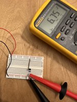
@ Dennis, I have a feeling I’m not connecting this correctly but wanted to share.
1. +V Drain
2. Connect Drain and Source w/ jumper
3. Connect 1 end of 100R to source and the other end of resistor to ground.
4. Result = 6.75vdc
Is this connected correctly?
1. +V Drain
2. Connect Drain and Source w/ jumper
3. Connect 1 end of 100R to source and the other end of resistor to ground.
4. Result = 6.75vdc
Is this connected correctly?
Attachments
Great! And Q2 bias resistor stays the same as in the kit?Let's not get too excited. The bias resistor for q1 is not very important to the performance. It's the resistor for q2 that's important. I have other examples where I omit the q1 bias resistor altogether. For the 2sk170 just set it at 0 or low value and don't worry about it

To answer my own question, again, with the help of cubicinchet, the bias resistor for Q2 should be considered, but as long as I choose 2SK170 Idss at about 10mA, the J113 should already be biased for this, with the resistor that the came with the kit.Hello rewind,
you have to adjust the bias - resistor of your CCS (the lower JFets in each buffer cell of the 6-24-XO) to run your active device (upper JFet in the schematic) to your desired 'sweet spot'.
Whatever your 'sweet spot' is - lowest possible distortion - or the sweetest sounding balance of H2/H3-
distortion?
I would use the J113 for the CCS and the LSK170 or 2SK170 as the active device in the buffer cell.
If you have bought the 2SK170 already, then you should know in which mA-range they should run.
Now you measure your J113 and adjust the bias-resistor of the J113 to get the desired mA-value
running through your active upper JFet.
There is some measuring and matching-work waiting for you!
Have fun! Enjoy the sound!
Cheers
Dirk
That sounds about right. If Q2/Q2 bias resistor were chosen to give about 10mA then you want to just pick Q1 with about 10mA (ideally at least as high as the Q2 current).
Since you know the value of the Q2 bias resistor, you can verify the Q2 current simply by measuring the voltage across the bias resistor.
Since you know the value of the Q2 bias resistor, you can verify the Q2 current simply by measuring the voltage across the bias resistor.
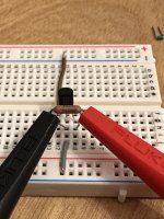
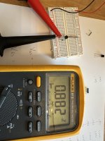
@ Dennis, I have a feeling I’m not connecting this correctly but wanted to share.
1. +V Drain
2. Connect Drain and Source w/ jumper
3. Connect 1 end of 100R to source and the other end of resistor to ground.
4. Result = 6.75vdc
Is this connected correctly?
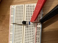
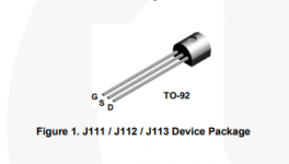
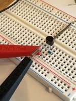
This is not correct. First of all, your jumper is actually connecting the gate to drain. I have attached the pinout for j113.
There is no jumper in the setup so you need to remove it. The resistor goes between the gate and source pins so in your photo #2, the two ends of the resistor should be on Row #10 and #11. The source pin is on Row #11 and that has to be connected to ground.
I suggest you take out the resistor and measure its resistance since it ran at almost half a watt (6.75V across 100 ohms) . The RN55C is likely fine but I still recommed first giving it a quick check. The jfet had about 0.2W but it should be ok since it's rated at 0.6W.
Attachments
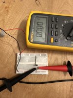
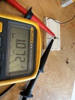
@Dennis, thanks for catching that…I had a late night.
I reshuffled the breadboard per your guidance. I tested the resistor and it was measuring at 100R but I swapped the J113 to be safe.
When I connect the DMM to the resistors it’s 0vdc. Do I need to connecting it differently or select a different setting on the DMM?
I reshuffled the breadboard per your guidance. I tested the resistor and it was measuring at 100R but I swapped the J113 to be safe.
When I connect the DMM to the resistors it’s 0vdc. Do I need to connecting it differently or select a different setting on the DMM?
Attachments
My apologies; the ground connection should be where the gate pin connnects to the resistor, so it should be at Row 10 and not Row 11.
Hopefully that didn't kill you j113.
https://www.diyaudio.com/community/attachments/1672358205837-png.1124354/
Hopefully that didn't kill you j113.
https://www.diyaudio.com/community/attachments/1672358205837-png.1124354/
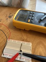
Got it. It now seems to be measuring reasonably.
You mentioned earlier that increasing resistance lowers current but it seems to do the opposite.
https://www.diyaudio.com/community/threads/diy-biamp-6-24-crossover.357657/post-7217439
100R=~1vDC
47R=~0.713vDC
249R=~1.6vDC
Am I measuring this incorrectly?
You mentioned earlier that increasing resistance lowers current but it seems to do the opposite.
https://www.diyaudio.com/community/threads/diy-biamp-6-24-crossover.357657/post-7217439
100R=~1vDC
47R=~0.713vDC
249R=~1.6vDC
Am I measuring this incorrectly?
Attachments
@Rewind, I believe he was confirming the way I was measuring J113 is incorrect.There was only one question there and the answer was a resounding "Yes!"
Can't wait for the finale.
I am standing ready with a solder gun to copy anything that works.
@Dennis Hui, I went back to your post #1258:
"The current flowing through the jfet is the voltage across R1 divided by R1."
I added a 475R between the gate and the source and measured ~1.822vDC. Therefore, 1.822/475 = 0.00383579 * 1000 = 3.84 mA?
"The current flowing through the jfet is the voltage across R1 divided by R1."
I added a 475R between the gate and the source and measured ~1.822vDC. Therefore, 1.822/475 = 0.00383579 * 1000 = 3.84 mA?
That is correct.
Similarly, for your three earlier measurements:
100R: ~1/100 = 10mA
47R: 0.713/47 ~ 15mA
249R: 1.6/249 ~ 6.4mA
This illustrates that the current decreases when you increase the resistor value.
Your measurements were correct, but your hadn't calculated the currents, so your came to the wrong conclusion.
Last edited:
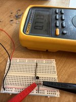
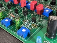
Much appreciated. Just to triple check that I’m measuring the 2sk170’s correctly, since I had so much trouble with J113, would you mind confirming my connections in the pic are correct?That is correct.
Similarly, for your three earlier measurements:
100R: ~1/100 = 10mA
47R: 0.713/47 ~ 15mA
249R: 1.6/249 ~ 6.4mA
This illustrates that the current decreases when you increase the resistor value.
Your measurements were correct, but your hadn't calculated the currents, so your came to the wrong conclusion.
Also, i know that the Q2 current is supposed to be a bit lower than Q1.
if all my Q1’s bias between 7.9 and 8.6mA, should I target Q2 to be roughly .5 to 1 mA less?
Should I be concerned if Q2 biased the same or a bit higher as Q1 (i.e. Q1 = 8.0mA and Q2=8.2mA)?
Attachments
Yes, it was, apparently. I am following the discussion with great interest.@Rewind, I believe he was confirming the way I was measuring J113 is incorrect.
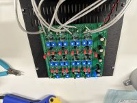
Well I bit the bullet and moved forward with the upgrade. Swapped all the Q1’s, making sure to cross the legs ensuring they didn’t touch. I re-tested the current of the original Q2 fets and all were measuring ~7.5mA using a 100ohm resistor. This allowed me to use my Q1’s measuring ~8mA and not hassle with tinkering/biasing Q2 anymore…it was already set using the fets and resistors included in the kit. No smoke after initial power up so I hooked it into my rig. Equipment has been off for a couple days; however, initial impressions (using cold equipment) are that is sounds pretty damn good. Looking forward to listening in the morning once everything’s warmed up overnight. Thanks everyone for the help.
Attachments
Congratulations!
For completeness, Papa wrote an interesting piece on biasing above Idss: https://www.diyaudio.com/community/threads/beyond-the-j-fringe.370957/#post-6617332
For completeness, Papa wrote an interesting piece on biasing above Idss: https://www.diyaudio.com/community/threads/beyond-the-j-fringe.370957/#post-6617332
Which value did you use for Q1 bias resistor? I am considering 4.7 ohm for Q1 bias resistor, giving a little more resistance than a jumper.Well I bit the bullet and moved forward with the upgrade. Swapped all the Q1’s, making sure to cross the legs ensuring they didn’t touch. I re-tested the current of the original Q2 fets and all were measuring ~7.5mA using a 100ohm resistor. This allowed me to use my Q1’s measuring ~8mA and not hassle with tinkering/biasing Q2 anymore…it was already set using the fets and resistors included in the kit. No smoke after initial power up so I hooked it into my rig. Equipment has been off for a couple days; however, initial impressions (using cold equipment) are that is sounds pretty damn good. Looking forward to listening in the morning once everything’s warmed up overnight. Thanks everyone for the help.
I just left the original 100R in place.Which value did you use for Q1 bias resistor? I am considering 4.7 ohm for Q1 bias resistor, giving a little more resistance than a jumper.
But if you replaced JFETS with 2SK170 with Idss at 8 mA, shouldn't you adapt the Q1 bias resistor to the new JFET? When I measured I got a lot higher Idss for the J113. But maybe I forgot to do the calculation with the highschool level electronics formula.I just left the original 100R in place.
Did you measure the Idss of the old J113 compared to the Idss of the new 2SK170 at the Q1 position?
- Home
- Amplifiers
- Pass Labs
- DIY biamp 6-24 crossover