Good Evening ,
Setting up the amplifier for the initial test without the output transistors, I have encountered the following problem. While going through the steps i came across these measurements:
A. The voltmeter monitoring the output voltage (millivolts) across R111A (TP107) and R111B (TP108) reads 793 mV steady.
B. the 4 LEDs besides D10 and D11 light up, maybe because I am using an 18V power supply.
C. I adjust the voltage between TP-1 and TP-2 with R11 to 5V.
D. I measure the voltage between TP-3 and TP-4 and it is 593 mV.
E .I measure the voltage between the TP-105 (DMM -) and the positive power rail connection and read 1.37V I use the TTC004B transistor for Q101. Likewise, I measure the voltage on the positive probe on the TP-106 (DMM +) and the negative probe on the negative rail and read 1.37V using the TTA004B for Q102.
F. However, measuring the voltage across the output, TP-100 (DMM +) and SPK GND (DMM -), TP-104 I do not get any reading no matter how R25 is adjusted.
I use MJE15032 (Q107), MJE15033 (Q108) and TTC004BQ (Q105), TTA004B (Q106).
Please, I would be grateful if you could give me any feedback that would help me solve this problem.
Looking at your test results things look ok except for this point.F. However, measuring the voltage across the output, TP-100 (DMM +) and SPK GND (DMM -), TP-104 I do not get any reading no matter how R25 is adjusted.
Are you sure that you have the temporary Jumper J-103 installed?
This is noted in the "Setup for initial testing" section and at point 14.A
Installing this jumper passes the voltage between R111A and R111B to the output trace until the output transistors are installed. It also completes the negative feedback loop.
Once the Output Transistors are installed it needs to be removed.
Good Evening ,
Setting up the amplifier for the initial test without the output transistors, I have encountered the following problem. While going through the steps i came across these measurements:
A. The voltmeter monitoring the output voltage (millivolts) across R111A (TP107) and R111B (TP108) reads 793 mV steady.
B. the 4 LEDs besides D10 and D11 light up, maybe because I am using an 18V power supply.
C. I adjust the voltage between TP-1 and TP-2 with R11 to 5V.
D. I measure the voltage between TP-3 and TP-4 and it is 593 mV.
E .I measure the voltage between the TP-105 (DMM -) and the positive power rail connection and read 1.37V I use the TTC004B transistor for Q101. Likewise, I measure the voltage on the positive probe on the TP-106 (DMM +) and the negative probe on the negative rail and read 1.37V using the TTA004B for Q102.
F. However, measuring the voltage across the output, TP-100 (DMM +) and SPK GND (DMM -), TP-104 I do not get any reading no matter how R25 is adjusted.
I use MJE15032 (Q107), MJE15033 (Q108) and TTC004BQ (Q105), TTA004B (Q106).
Please, I would be grateful if you could give me any feedback that would help me solve this problem.
Please post a picture.
This is really the correct tin/lead solder as it is the eutectic ratio and will not change composition when it solidifies. Leaded solders are generally easier to work with but they are banned in commercial applications. There are some low melting lead-free solders, but the ones I've seen have bismuth, which I'm not sure is that much better environmentally.I prefer 63/37 rosin myself, 0.8mm or .032" for majority of work
Hi everyone,
I ordered a set of boards (3-3) and now im trying to digest all the many choices i have to make.
I have decided to go with SMPS for power and im considering the Hypex SMPS1200A400
Is this a suitable choice or is it overkill? Any alternatives out there?
Thanks in advance")
I ordered a set of boards (3-3) and now im trying to digest all the many choices i have to make.
I have decided to go with SMPS for power and im considering the Hypex SMPS1200A400
Is this a suitable choice or is it overkill? Any alternatives out there?
Thanks in advance
Hypex SMPS1200A400 was my choice and I built my Wolverine using it. Might be it's a bit overkill, but for sure it gives the amp all the power it needs. And above all it seems there's no difference in sound with respect to linear PSU. Indeed my concern in using SMPS was basically about bass. SMPSs are not huge as linear counterparts, so one is brought to think that something couldn't be that much powerful. But it's a completely wrong idea. Bass instead is fast and powerful and easily I can get live sound pressure in my listening room, so that it frightens me!
Gaetano.
Gaetano.
Thanks for the post @kaan as I to am currently wrestling with similar decisions
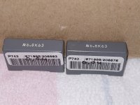
@fireanimal, please could you share which Cobra S2 variant you opted for as I'm busy planning my build whilst my boards are in flight:
Regards to all.
@fireanimal, please could you share which Cobra S2 variant you opted for as I'm busy planning my build whilst my boards are in flight:
- Output Voltage (Dual Rails)
- AUX Voltage (Regulated)
- Driver voltage
- Primary Capacitors
- Voltage regulators for (+-AUX)
- Voltage regulator for (VDR)
- Standby power supply voltage
- Secondary Capacitors
Regards to all.
Most of the other options are for class d amps. You are only concerned with rail voltage depending on your output transistors. Standard caps are fine you don't need to spend extra. The base S2 with either +-63 or +-71 will work just make sure you chose the proper transistors
Thanks for the feedback
I guess ill go with the SMPS1200A400 then.
@ghitus did you need to add cooling to the metal plate on the side?
Do you have a picture of the layout?
Did you split the single +-Gnd output to the two channels?
Did you implement a standby button?
Thanks in advance
-Klaus
I guess ill go with the SMPS1200A400 then.
@ghitus did you need to add cooling to the metal plate on the side?
Do you have a picture of the layout?
Did you split the single +-Gnd output to the two channels?
Did you implement a standby button?
Thanks in advance
-Klaus
Hi Klaus, I live in Bari, the town of Santa Klaus, nice to meet you!!
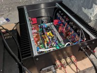
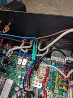
Unluckily my pics are not that good. What I did was to split of course V+ and V- and to connect the SMPS ground to a T shaped PCB which acts as a star ground. As regards the standby button, I opted for the Hypex softstart which can be used to switch on and off the amp both by a latching and a momentary pushbutton.
I hope it helps.
Gaetano.
Attachments
Thanks for your response,Looking at your test results things look ok except for this point.
Are you sure that you have the temporary Jumper J-103 installed?
This is noted in the "Setup for initial testing" section and at point 14.A
Installing this jumper passes the voltage between R111A and R111B to the output trace until the output transistors are installed. It also completes the negative feedback loop.
Once the Output Transistors are installed it needs to be removed.
I have already installed the Jumper J-103. I have decided to build the second channel of the amplifier more carefully , and i will repeat the measurements and i will upload photos .
- Home
- Amplifiers
- Solid State
- DIY Class A/B Amp The "Wolverine" build thread