In post #20 Nelson said a bit under 3mA, so you can try a lower value resistor. He also said that it is not critical.Hello! I have R7=680ohm/V=1.12/I=1.6mA.
This is good?
Post #20
I would like to incorporate a pair of these into MOFO's to bump up the gain then run them with a waynes preamp.
My Mofo monoblocks are being run off of two 19V Dell supplies with 6.7A.
Could I run the Front ends off the same 19V supplies or should I get something with more voltage to run the two boards?
My Mofo monoblocks are being run off of two 19V Dell supplies with 6.7A.
Could I run the Front ends off the same 19V supplies or should I get something with more voltage to run the two boards?

The correct concept but sorta missed the target.I recently did a small test, a common source on which I tried 3 types of drain resistors, no name metal film, rn55 and caddock mp915.
The caddocks were the lowest thd followed by the rn55 with 2x the thd and on the last place there were the no name with 4x thd of the caddocks.
What you are speaking of is resistor distortion (mostly 3rd HD) caused by resistor thermal effects as shown in PPM on the resistor datasheet.
RN55 resistors typically come in three PPM categories; 100PPM, 50PPM and 25PPM. Resistors heat and cool at a rate of 2 times the frequency of the applied audio signal. When the thermal mass of the resistor resistive element is constant 100PPM parts have 4 times the distortion of 25PPM parts.
RN60 resistors also come in three PPM categories; 100PPM, 50PPM and 25PPM. RN60 resistors produce less distortion because of greater thermal mass, reduced temperature change compared to their smaller RN55 brothers.
Thanks DT
Definitely not a bad idea to experiment with different psu topologies.
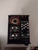
But, that layout might be an issue with signal and power wires not playing nicely with each other.
Try that setup with the transformer placed outside the chassis. If you like it, maybe look for a larger chassis for better layout options.
But, that layout might be an issue with signal and power wires not playing nicely with each other.
Try that setup with the transformer placed outside the chassis. If you like it, maybe look for a larger chassis for better layout options.
Better layout would have the FE boards on the right side, on the same side as the RCA jacks and pot. Place the PS board and transformer on the left side, with the transformer at the front, far away from the signal wires and jacks. Place the AC/IEC connector at the left side of the back panel.
Have you actually compared ? What’s the improvements?Oh yes I have used VRDN with my FE initially but later moved to Salas dual mono as I had the psu boards as well as toroidals
Much better improvement over smps for sure.
I’m using a 48Vdc SMPS + Mark’s SMPS filter and it’s very good.
Thanks
Eric
Hi guys, I recently purchased a set of the FE 2022. I noticed that it is the V0R1 version, which I understood is slightly different from the V0R0. There are a P1 trimpot and a C6 cap which are not mentioned on Nelson's original BOM. Could someone of you please clarify this particular?
Thank you very much and regards.
Gaetano.
Thank you very much and regards.
Gaetano.
Here is post 686 that I distilled into a single sheet PDF for my own reference. Papa's words slightly edited.Hi guys, I recently purchased a set of the FE 2022. I noticed that it is the V0R1 version, which I understood is slightly different from the V0R0. There are a P1 trimpot and a C6 cap which are not mentioned on Nelson's original BOM. Could someone of you please clarify this particular?
Thank you very much and regards.
Gaetano.
Attachments
Far from being a complaint: Just got a kit and they are exactly as they are represented in the STORE.
The reason for writing is there had been a post or two that made it sound like ALL of the needed resistors were included with the kit. Thinking this was true, even though the store says nothing to this effect, I did not bother to order the needed resistors. So UPS gets another delivery fee from me.
Hope to have it playing music over the weekend.
Thanks for the kit to our great patron and the DIY STORE.
One thing that I wonder about - is with many using power supplies greater that 50 volts should caps C4 and C5 rated at 25 volts in the BOM be uprated to reflect the power supply being used?
- Home
- Amplifiers
- Pass Labs
- DIY Front End 2022