Hello out there,
I have lowered the value of R7 - made a second 330 Ohm resistor in parallel. I have now 165 Ohm and there are 0,86 V running over R7.
So the CCS (Q3) is now at approximately 5,2mA. Offset at output was trimmed to below 0,5mV. Sounds better- I think.
Cheers
Dirk
I have lowered the value of R7 - made a second 330 Ohm resistor in parallel. I have now 165 Ohm and there are 0,86 V running over R7.
So the CCS (Q3) is now at approximately 5,2mA. Offset at output was trimmed to below 0,5mV. Sounds better- I think.
Cheers
Dirk
if there is positive DC offset at output node, R7 must be increased, to decrease Iq of Q3 (LTP JFet CCS)
if there is negative DC offset at output node, R7 must be decreased, to increase Iq of Q3 (LTP JFet CCS)
again, leave R6 original value, do not mess with circuit OLG
if there is negative DC offset at output node, R7 must be decreased, to increase Iq of Q3 (LTP JFet CCS)
again, leave R6 original value, do not mess with circuit OLG
Tried so many combinations of R6 and R7.
Now everything backed to the values of Pass' reference circuit, only changed R7 to 1K. Now the offset reduced to 0.1V.
Looks like in the correct direction.
Now I understand why the essential kit has to have R7 and R8 and semis picked by Mr.Pass.
Now everything backed to the values of Pass' reference circuit, only changed R7 to 1K. Now the offset reduced to 0.1V.
Looks like in the correct direction.
Now I understand why the essential kit has to have R7 and R8 and semis picked by Mr.Pass.
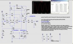
The smallest distortions in the presented scheme can be achieved by changing R6 within small limits. If anyone needs it here.Spice file for Nelson's circuit to play with
Attachments
Depends on the output transistors. The article shows a 10 Kohm in parallel with 1 nF load, @ 2.8V and the distortion goes
from around .0025% at 1 KHz to .005% at 20 Khz. As you increase the capacitance at 20 KHz it climbs to .01% at 2 nF
and .05% at 5 nF. Above this capacitance and/or amplitude it continues to climb, showing a negative phase 2nd harmonic.
In a MUFF the Cgd of a single output is the dominant load, and in the parts I have used ranges from 150 pF for the IRFP240
Mosfet to 200 pF for the Sony VFET to 800 pF for 2SK77 VFET to 3 nF for the 2SK182.
The 2SK182 is a bit of a stretch, but it depends on how hard you push it. I haven't noticed any subjective issues that I
would attribute to Gate capacitance, but I haven't tried it on an X1000...
Just add a buffer after the second stage, like in the opamp article :
https://www.passdiy.com/pdf/diyopamp.pdf
Fig. 14
Patrick
https://www.passdiy.com/pdf/diyopamp.pdf
Fig. 14
Patrick
You can use this to drive the M2 output stage with IRFP240/9240.
Especially if you close the outer loop.
https://www.diyaudio.com/community/...in-class-a-b-and-maybe-a-power-whammy.390636/
Quote from the article :
"The J113 and KSA992 have been shown to stand up to 70 volts maximum in testing,
but I am suggesting that a 50 volt supply is appropriate and allows use of 2SK170 type and other Jfets as well."
So maybe you dare to use +/-25V supplies.")
Patrick
Especially if you close the outer loop.
https://www.diyaudio.com/community/...in-class-a-b-and-maybe-a-power-whammy.390636/
Quote from the article :
"The J113 and KSA992 have been shown to stand up to 70 volts maximum in testing,
but I am suggesting that a 50 volt supply is appropriate and allows use of 2SK170 type and other Jfets as well."
So maybe you dare to use +/-25V supplies.
Patrick

I have used my +-20V supply - so, I am 5 steps/ volts from the positive target-rail as well 5 steps/ volts from negative target-rail away.
For me, this means 10 steps to F.A.B. - membership minimum...
Have fun playing with this circuit! Simple and good - very similar what I did a few years ago with ZVN/ZVP3310 and added CCS from the DIY Op Amp-article. https://www.firstwatt.com/pdf/art_diy_opamp.pdf
Railvoltages were +-32 V! I've built fig. 4 / page 7.
Cheers
Dirk
- Home
- Amplifiers
- Pass Labs
- DIY Front End 2022