@solhaga s images where he shows that simple foam is of course softer than the corrugations and will give way made me rethink some things.
I think my TPU suspension is an overly complicated starting point. I should start simple, start with what others have already tried and found to be working well enough. Therefore I should start with a simple PU foam suspension. And only when I have a working speaker which performs well enough then I can start playing around with the TPU suspension to see if it improves things or not.

I started browsing the web for suitable soft and porous PU foam which is 5 mm thick, and one of the the top results was the foam for speaker fronts. That got me thinking of one setup which would be cool to try...
Instead of having the suspension at the sides, what if I added foam suspension in between the magnets? With the suspension on the sides and the actual force being applied in the middle the corrugations act as a leaver. There is a change that it would be better if the suspension and the force was exactly aligned, which it would be if the suspension was in between the magnets and thus the membrane coils would all be directly in contact with the suspension. Many manifacturers already add dampening material inside the driver to reduce resonances and this foam will probably do that too. And since the effective disance ctc-distance between suspensions is reduced from 55mm down to 10 mm I could get away with less deep corrugations which would improve linearity.


I will of course still start with a normal side foam setup since I need a benchmark to start with, but it would be cool to try afterwards
I think my TPU suspension is an overly complicated starting point. I should start simple, start with what others have already tried and found to be working well enough. Therefore I should start with a simple PU foam suspension. And only when I have a working speaker which performs well enough then I can start playing around with the TPU suspension to see if it improves things or not.
I started browsing the web for suitable soft and porous PU foam which is 5 mm thick, and one of the the top results was the foam for speaker fronts. That got me thinking of one setup which would be cool to try...
Instead of having the suspension at the sides, what if I added foam suspension in between the magnets? With the suspension on the sides and the actual force being applied in the middle the corrugations act as a leaver. There is a change that it would be better if the suspension and the force was exactly aligned, which it would be if the suspension was in between the magnets and thus the membrane coils would all be directly in contact with the suspension. Many manifacturers already add dampening material inside the driver to reduce resonances and this foam will probably do that too. And since the effective disance ctc-distance between suspensions is reduced from 55mm down to 10 mm I could get away with less deep corrugations which would improve linearity.
I will of course still start with a normal side foam setup since I need a benchmark to start with, but it would be cool to try afterwards
Last edited:
Interesting.I think the foam for speaker fronts will be to stiff.
What source for foam are you using? I guesstimate we want something in the 15-25 kg / m3 range but I have trouble finding sources, and the ones I do find don't publish the density.
Last edited:
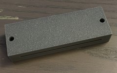
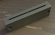
If you're gonna make several tests with different suspensions, it could also be interesting to test the Occam's Razor's solution;
simple dust sealing strips like this one:
View attachment 1320297
Might be worth a shot to try the most basic foam too.
But yes my plan is to first build a working version where I don't try to be smart at all. A version where I just copy a known working version of what @WrineX has built in one of his amazingly helpful videos. The plan is for that reference version to be:
And then do lots of small experiments where for each experiment I change a single part of the driver. And then iterate until I am satisfied.
On top of my head I want to try:
But yes my plan is to first build a working version where I don't try to be smart at all. A version where I just copy a known working version of what @WrineX has built in one of his amazingly helpful videos. The plan is for that reference version to be:
- straight
- push-pull
- foam suspension
- 5 rows of magnets glued on the 1.5 mm steel sheets without any extra support
- membrane with a filled plane of aluminum but with cuts strips to form the coil traces. But basically keep undriven aluminum areas in between the magnet gaps to make it stiffer.
And then do lots of small experiments where for each experiment I change a single part of the driver. And then iterate until I am satisfied.
On top of my head I want to try:
- single ended
- different foam suspensions
- speaker grille foam suspension around the coil traces in the magnet gaps
- printed TPU rubber suspension
- membrane with only coil traces, no filled areas
- membrane with smaller filled areas
- combined width of the traces vs magnet gap, how many % should they cover?
- 7 rows of magnets
- "default" membrane
- membrane where I add high frequency shading to the outer traces (shading parallelled with a lowpass). The goal would be to have my cake and eat it too: better low frequency response without compromising the high end.
Model for the magnet gluing jig done, now I just need to print 4 more so I can start gluing. I have enough magnets for 18 plates of that size (12x5x3mm).
I'm planning to use 1h epoxy so will glue in batches. And while the glue is drying the plan for the weekend is to start playing around with the Silhouette Cameo 5 and try to cut some aluminum.
Since I have 30um aluminum foil (but have bought 20um too that is on the way) with adhesive on one side already I need to think about how I can transfer it to the mylar. I have bought some vinyl transfer sheet but who knows if it will stick well to aluminum, but I guess I will find out
I have bought som 3M 77 & ReMount as backup in case the best way forward is to do as you others are doing, ReMount to make the aluminum stick while cutting and then apply 77 to the mylar and stick them together. Then carefully peel the mylar off off the cutting board and add chalk to make 77 not covered by aluminum non sticky.
Attachments
Using jigs when gluing with epoxy can be a little tricky; beware of getting epoxy on the jig.
Use the test cut a lot, you can move the test area with the arrows or do it on the machine.

Do you use the autoblade? The knife can be adjusted from 0.1 mm to 1 mm.
The force can be hard to dial in so do a lot of testing.
There's an optimum speed; too fast and the knife will rip the aluminium, too slow and you will fall asleep.
I have never cut that thick aluminium foil; I've only used 7 and 10 µm on a water dissoluble paper backning.
Will your backing be water dissoluble?
I think it will be best if you do the weeding while on the cutting mat.
When I used the cutting mat with my small AMT membranes, I used an additional paper layer so that I could apply the mylar to the aluminium.
Then I put the it all in water to dissolve the paper.
Beware of the ReMount glue, sometimes it is not that remountable.
Use the test cut a lot, you can move the test area with the arrows or do it on the machine.
Do you use the autoblade? The knife can be adjusted from 0.1 mm to 1 mm.
The force can be hard to dial in so do a lot of testing.
There's an optimum speed; too fast and the knife will rip the aluminium, too slow and you will fall asleep.
I have never cut that thick aluminium foil; I've only used 7 and 10 µm on a water dissoluble paper backning.
Will your backing be water dissoluble?
I think it will be best if you do the weeding while on the cutting mat.
When I used the cutting mat with my small AMT membranes, I used an additional paper layer so that I could apply the mylar to the aluminium.
Then I put the it all in water to dissolve the paper.
Beware of the ReMount glue, sometimes it is not that remountable.
Yup, there is a small gap from where the glue will be and the jig but I might increase that. Also thinking of spraying the jigs with silicone to reduce the risk of accidents.Using jigs when gluing with epoxy can be a little tricky; beware of getting epoxy on the jig.
Do you use the autoblade? The knife can be adjusted from 0.1 mm to 1 mm.
The force can be hard to dial in so do a lot of testing.
There's an optimum speed; too fast and the knife will rip the aluminium, too slow and you will fall asleep.
I have never cut that thick aluminium foil; I've only used 7 and 10 µm on a water dissoluble paper backning.
Will your backing be water dissoluble?
I think it will be best if you do the weeding while on the cutting mat.
When I used the cutting mat with my small AMT membranes, I used an additional paper layer so that I could apply the mylar to the aluminium.
Then I put the it all in water to dissolve the paper.
I have an autoblade and a 1mm ratchet blade, I'll have to try an see what blade works best.
On my current 30 um foil I don't think the backing is water dissoluble. Do you mean that the foil came preapplied on a water soluable backing or that you have glued it onto a water soluable backing for support when printing?
Good to know, thanks!Beware of the ReMount glue, sometimes it is not that remountable
And I will have to put some brakes on the idea on gluing the magnets. I need to validate some things first. I have understood correctly that the polarity should be as per the following image?

Which means that lengthwise the magnets will not stick nicely but rather try to repel each other. When placing them on the steel the magnets are short enough that the attractive force to the steel plate is not enough to overcome the repelling force lengthwise so I will definently need the magnets to stay in the jig when gluing.
Also, I'm a bit scared of messing up the magnet polarity somewhere in the driver so I'm leaning towards painting the exposed side of the magnets. I calculated and if I go 5 rows of 12x5x3mm magnets I need 2600 magnets for 2 160cm tall push-pull drivers. I would definently mess up the polarity at least somewhere so painting would give me some peace of mind and also help as a sanity check to ensure consistency.
I'm thinking I could first place magnets in a flat 1 layer sheet

Then spray the top with white primer.

And then add a 3d printed jig where every odd hole is covered and spray some red paint.

The bottom would remain unpainted to get the best bond between the steel and the magnets.
But a problem with painting them in the above pattern is that it is quite fiddly to orient the magnets into a flat sheet since they are much stronger at the poles. It would take a lot of time to do so with 2600 magnets since just takes a little nudge and they will overcome the weaker edge to edge attraction go back to being pole to pole.
An easier way to paint them that is probably good enough is to just have them in a large block pole to pole but then use masking tape to mask the bottom of each magnet row, + top and sides and then spray a red coat of primer.
A benefit of this way is that they are all the same. With the method in the post above I would get 1:1 of white topped = S, red topped = N magnets but in practice I need 3:2 magnets to be of a certain orientation since I have 3 + 2 rows of each orientation.
Attachments
Yes.Do you mean that the foil came preapplied on a water soluable backing.
Yes. The plates will have repelling magnets but with the opposite polarity for every other column.I have understood correctly that the polarity should be as per the following image?
When I mount the magnets, I test them in my palm against a reference magnet. I use no paint or marking.
Before I move on to the next column, I double check the polarities.
But I guess that method can get a little problematic with that many and such small magnets.
Since the magnets put a spanner in the works I decided to rethink more parts...
With the magnets repelling so strongly I need to redesign the glue jigs and all in all it would be a lot of time to fiddle with the small 25mm tall steel plates so I have decided to ditch them and go on to curved plates. With the curve they will naturally get more stiff too so I don't have to think about solutions for that either.
I have also been inspired by you solhaga, I am leaning towards bumping the steel thickness to 2mm. I printed some samples of the steel plates solid on my printer to validate that all the holes align when they are bent and I printed both 1.5mm and 2mm thick "steel plates" and the 2mm is just so much stiffer.


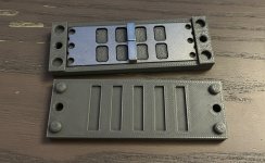
I have also decided to steal your idea of having the steel supports on an offset to ensure they all don't align and cause noise:

And in case someone is counting rows they might realize that these plates have 5 rows of magnets but 7 holes...
I am planning to order test parts where the outer holes are solid which is the standard in addition to this setup but the thought behind the holes are: Along the edge of the membrane I need to have aluminum to stiffen it in the suspension. And there is still a magnetic field there, although weaker since only magnet on 1 side. And since the magnet field is there, the aluminum is there I might as well see what happens if I drive current through the aluminum. This is basically what the PDR tweeters do, they have 4 rows of traces but only 3 rows of magnets.
I'm not sure it would increase efficiency but I believe it would increase the low frequency output slightly. I'd need to add a metal / 3d printed mesh to the holes such that the suspension is supported evenly and not just on the supports. But in the end I have a hunch that low frequency sounds should pass right through the foam suspension so would give more output.
With the magnets repelling so strongly I need to redesign the glue jigs and all in all it would be a lot of time to fiddle with the small 25mm tall steel plates so I have decided to ditch them and go on to curved plates. With the curve they will naturally get more stiff too so I don't have to think about solutions for that either.
I have also been inspired by you solhaga, I am leaning towards bumping the steel thickness to 2mm. I printed some samples of the steel plates solid on my printer to validate that all the holes align when they are bent and I printed both 1.5mm and 2mm thick "steel plates" and the 2mm is just so much stiffer.
I have also decided to steal your idea of having the steel supports on an offset to ensure they all don't align and cause noise:
And in case someone is counting rows they might realize that these plates have 5 rows of magnets but 7 holes...
I am planning to order test parts where the outer holes are solid which is the standard in addition to this setup but the thought behind the holes are: Along the edge of the membrane I need to have aluminum to stiffen it in the suspension. And there is still a magnetic field there, although weaker since only magnet on 1 side. And since the magnet field is there, the aluminum is there I might as well see what happens if I drive current through the aluminum. This is basically what the PDR tweeters do, they have 4 rows of traces but only 3 rows of magnets.
I'm not sure it would increase efficiency but I believe it would increase the low frequency output slightly. I'd need to add a metal / 3d printed mesh to the holes such that the suspension is supported evenly and not just on the supports. But in the end I have a hunch that low frequency sounds should pass right through the foam suspension so would give more output.
No reason reason other than that I unchecked some to make the image less cluttered like this:Why are there magnets on one side only towards the edge of the membrane?

The plan is of course to go push pull with dual plates. Very similar to yours, except for the curve and 3mm xmax vs 4mm in yours the dimensions are pretty much the same too.
I didn't mean in the picture but this:
And there is still a magnetic field there, although weaker since only magnet on 1 side.
oooh, now I get what you mean.I didn't mean in the picture but this:
Mostly because there is only so much room, if I add another row of magnets the driver would need to be wider.
Let us start with the normal setup. The outer holes are normally not open but closed, like they are in your planar.

The orange blocks are the foam suspension. Since the screws are in the yellow edge bit there is no room for another row of magnets. But we could, probably while reducing the efficiency somewhat bump the radiating area by instead of just having blocks of foil along the suspension to route traces there too like this:

Which is kinda how this Neo3PDR clone works. Although this driver doesn't have the outer holes do double duty as suspension which I want to try. But the suspension should at most act as a lowpass filter methinks.


There are 4 rows of traces but only 3 rows of magnets. The outer rows don't add as much output as if there was magnets on both sides but it does add some output, probably more in our cases since we have a stiffer corrugated membrane. Or at least more on the low end.
Ok. Seems like they don't care about non linearity and compression effects then.
It definently isn't as linear no. The question is just how big the tradeoff is. It might be that the increase in surface area is enough to offset the disadvantages such that the end result is equal-ish sensitivity but less distortion at the same SPL. Would have to be tested!
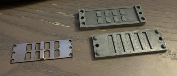
I'm leaning towards testing the 3 following setups:
1. First is the standard setup. Almost a carbon copy of yours solhaga but with a thicker membrane and curved. Unless I mess up the curve or something major this is guaranteed to work great for my use cased based on your measurements solhaga.

2. Then the first weird setup. Exposed holes above and below the suspension. Not rendered is that there would need to be a grille in between the steel and the foam to evenly distribute the force on the membrane:

3. And lastly a combination of both. Grille not rendered again. Still radiating audio through the suspension but with magnets on either side. More efficient than the standard setup on the low end since it has less membrane mass? Also less wide which would be nice.

Yes, it's always to get some empirical data., even if the experts says it will not work. Look how the penicillin was discovered (and not invented).
- Home
- Loudspeakers
- Planars & Exotics
- DIY midtweeter planar, physically curved and shaded to be used in a dipole CBT