..Maybe I have "worked" the trimmer..
Do you find time for trimmer resistances mesurements ?
How much Ohm's will be the equivalent resistors pair's on both channels ?
") Greetings
GreetingsI have ordered 10x 3386P, 25k Bourns trimmers from RS Components.
I think I will try first putting a new trimmer in but I will measure the old when I pull it out. Then I can communicate the values for the two resistors
The country code was CR.....as I remember.....so Costa Rica?
Hope they are good!
They will be shipped from GB and is estimated to take about a week (I think because GB is not EU anymore).

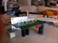
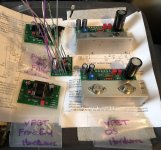
Soo, a couple of hours off this morning at home, decided to solder the boards.
As said, late to the party re parts reception, plus my soldering skills (and many other skills LOL) are way behind the usual posters here, so I keep low profile respectfully and don't waste your eyesight with my poor work...
Anyway, was too leazy to install the holder/vice or the octopussy multiarm board holder, and decided to do it quick and dirty directly on the table. Found as ever that Blutack was my friend as third hand & Co and that amazingly a Tic Tac big box had nearly the ideal sizes to enable a very quick and easy soldering job. I have no share with them, in fact they may ruin my health rather
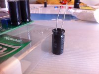
Last but not least, I thought about the 20V adjustment and have limited faith in my ability to measure repeteadly an open running somewhat cramped unit with a 3y old by my side. I have a steady hand for SMD, but given the rarity of the VFET I thought I may solder the big resistor differently to enable me an easier access to the positive voltage point to be adjusted. Yes, there are nice probe for that that retract in case they get lose, but I have only big crocodile types so far.
I hope I did nothing wrong mounting the resistor in what I thought would be a clever way, the extra path being short and anyway the same for both channels, while from a temp gradient POV things look Ok to me, and of course it comes for free and is easier to fit than a lug. OK, it might not look fantastic, but the main user of the amp, my wife, told me: who cares, nice from the outside and no one will ever look inside whatever, but you
Yes, I know it is not at the Zener, as recommended but if you follow the schematic this should be an equivalent measurment point...
Need now to think about cabling to enable quick connections, and as I like soldered connections, I am thinking about fitting " large component legs" I have left over into some of the holes for cables, acting a bit as tie-down ***** on which I could easier solder and desolder tiny cables without hopefully ruining anything on the board while releaving some stress from the cables.
Just thinking out loud, open minded
Enjoy music
Claude
As said, late to the party re parts reception, plus my soldering skills (and many other skills LOL) are way behind the usual posters here, so I keep low profile respectfully and don't waste your eyesight with my poor work...
Anyway, was too leazy to install the holder/vice or the octopussy multiarm board holder, and decided to do it quick and dirty directly on the table. Found as ever that Blutack was my friend as third hand & Co and that amazingly a Tic Tac big box had nearly the ideal sizes to enable a very quick and easy soldering job. I have no share with them, in fact they may ruin my health rather
Last but not least, I thought about the 20V adjustment and have limited faith in my ability to measure repeteadly an open running somewhat cramped unit with a 3y old by my side. I have a steady hand for SMD, but given the rarity of the VFET I thought I may solder the big resistor differently to enable me an easier access to the positive voltage point to be adjusted. Yes, there are nice probe for that that retract in case they get lose, but I have only big crocodile types so far.
I hope I did nothing wrong mounting the resistor in what I thought would be a clever way, the extra path being short and anyway the same for both channels, while from a temp gradient POV things look Ok to me, and of course it comes for free and is easier to fit than a lug. OK, it might not look fantastic, but the main user of the amp, my wife, told me: who cares, nice from the outside and no one will ever look inside whatever, but you
Yes, I know it is not at the Zener, as recommended but if you follow the schematic this should be an equivalent measurment point...
Need now to think about cabling to enable quick connections, and as I like soldered connections, I am thinking about fitting " large component legs" I have left over into some of the holes for cables, acting a bit as tie-down ***** on which I could easier solder and desolder tiny cables without hopefully ruining anything on the board while releaving some stress from the cables.
Just thinking out loud, open minded
Enjoy music
Claude
Attachments
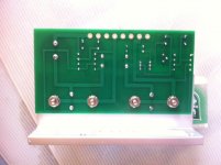
Finally finished populating all my boards and the wiring on the PS Filter 
Now I actually get to start working with the case and wiring.
Spent a half hour searching the thread and re-reading the drama about whether or not to connect the 2 outer pins on the power inlet socket to a ground lug on the PS Filter stand-off. So it seems I’m leaving them “flying in the air”.
No quirky first run boards in my kit.
Hope I’m not forgetting any other issues.
Onwards
Attachments
..Yes, there are nice probe for that that retract in case they get lose, but I have only big crocodile types so far.
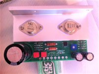
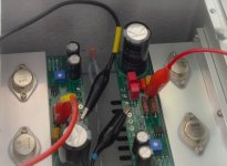
Congratulation on Your work in progress.
Big crocodile can be used , we get speace on this Passworks design pcb
Attachments
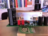
Well... You have far more faith than me on these devices, LOL
Do you see any downside doing what I did with the resistor?
On another note, having just soldered the bits today, it seems to me you have very different parts re Zener and other surrounding bits (not the big resistors obviously) - Is it me?
I defo can't use the standard crocos to catch the Zener's leg, I could barely - safely - catch the leg of the next resistor that comes already soldered, but with short leg on this side, hence the idea to make a big leg / loop with the second resistor, the one we have to solder anyway ourselves...
Last but not least, I didn't look at the schematic of the wiring yet, but didn't realise that there was a free space for the Ground... that neans no need for my tie-down c*, indeed I could use a croco directly as you did _ Brillant, thanks!
Thanks again for that useful pix and your kindness
Claude
Yes, we want to hear about Rafa's build?
Kit parts must have arrived?
I'm a bit scared to put the store and Jason in a tough situation... short answer is yes, parts have arrived! Big shoutout to Jason and thanks for going a very, VERY long way beyond and above his duty. I mention my concern, because if everyone needs the amount of time and effort I tasked from Jason, he would not be able to live a semi-normal life.
But yes, I have them with me, I have asked for a week vacation starting the 12th. Not sure I am going to be able to work on it before that, as much as my hands itch to start soldering!
I'll keep you posted, thanks for the interest!
Rafa.
 Enjoy
Enjoy- Home
- Amplifiers
- Pass Labs
- DIY Sony VFET Builders thread