Hallo HelmutHolz,
if this is a DPST switch (two-pole, just on or off), your wiring looks suspicious to me. In my switch, the two left tabs do belong together, and the two right tabs.
Please test the working of the switch first without the PSU connected ...
Best regards, Claas
if this is a DPST switch (two-pole, just on or off), your wiring looks suspicious to me. In my switch, the two left tabs do belong together, and the two right tabs.
Please test the working of the switch first without the PSU connected ...
Best regards, Claas
Hallo HelmutHolz,
if this is a DPST switch (two-pole, just on or off), your wiring looks suspicious to me. In my switch, the two left tabs do belong together, and the two right tabs.
Please test the working of the switch first without the PSU connected ...
Best regards, Claas
also thought the same
Is smaller values okay too?
Yeah, smaller values are fine.
I could be wrong, but if you take the cap value and the nominal impedance of your speakers, you can calculate a HP roll-off frequency for the bypass cap. Essentially the frequency range the cap would be 'in play.' For instance, with 8 ohm speakers and this 75uf cap, I get a roll-off frequency of 245 hz – meaning I'd expect the cap to have some influence in the range above that frequency (and below to a lesser extent, considering roll-off). I'm positive its more complex than that, but that's how I wrap my brain around it.
That said, if someone who actually knows if thats the case or not could chime in, I'd feel better.
There's no dispute that the output cap acts as a first order filter with your speakers. What I'm trying to determine now (researching based on Tungsten's suggestion) is – when paralleling caps for the output – if my rule of thumb is applicable or not (#215)
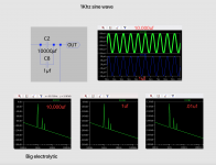
Ok, I'm barely past the point of knowing how to open Spice, but I tried to run a simple simulation on my lunch hour to figure this one out. I believe my earlier assumption was wrong. It would appear once the two caps of different sizes are paralleled, they attenuate frequency as one large capacitor.
I used a 1Khz sine wave and looked at an FFT across the 10,000uf cap, a 1uf cap, and a .01uf cap. Based on my earlier assumption, the .01uf cap would have shown disproportional attenuation of the 1khz tone (as compared to the larger valued capacitor), but it doesn't. In fact, the 1khz and its harmonics appear exactly the same – proportion-wise – across each cap.
Instead, the difference appears in the amount of current each capacitor passes. You can see a comparison of 10,000uf vs 1uf (look at the scale). Likewise, look at the overall level (see scale) of each of the FFTs. Where the 10,000uf capacitor is contributing -10db, the 1uf cap is contributing -90db, and the .01uf cap is contributing -130db.
In summary, it seems a smaller bypass capacitor is impacting the overall freq. range (as determined by the HP when calculated as one, large cap), its just passing much less current than the larger cap. In other words, same voltage, different amounts of current.
I'm not sure if all these pseudo-science ponderings are true, but it should at least give people that actually know this topic something to respond to
")
Attachments
Looks good! Chassis number 180 was finally delivered yesterday
codyt,
Good for you on taking the first steps to learn SPICE simulation.
Getting correct and relevant results will depend on using accurate models for the components in question. Unfortunately, capacitors are one of the more misunderstood elements in circuit design. Rather than the ideal mathematic constructs we tend to use, real life capacitors have a number of parasitic elements that are crucial to their performance. That is why we use different types (film, ceramic, electrolytic) for different applications, in addition to different values.
Capacitors are best thought of as notch filters. Their real-world impedance includes resistive and inductive components. The lower edge of the pass band is set by the capacitance and the upper edge by the various parasitic inductances. Sometimes the resistance is published, sometimes not. The inductance is rarely, if ever, published. You may have noticed the presence of unexplained resistances in other SPICE schematics. These are usually an attempt to model the more complex impedance of real-world caps.
So when we start adding parallel capacitors, what we are really doing is trying to flatten the bottom of the pass band which is established by the main element. In the case of a big 10,000 uF electrolytic, the lower edge of the pass band is usually good. The upper edge, and the consequent phase response, is not always conducive to best performance. That is why we frequently see smaller value film caps stacked in parallel with big electrolytics. The VFET amp OS uses a 0.33 uF film (polypropylene) cap in parallel with the big Rubycon for this purpose. Adding another relatively small electrolytic in parallel helps to maintain the 'bottom' of the pass band so it doesn't show any peaks between the lower and upper edges. A rule of thumb that I like to use is to keep the different values a decade or more apart. (This helps prevent resonance induced by the parasitics.) So 10,000 uF + 470 uF + 0.33 uF seems like a good combination.
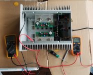
#184 is done and tested.
Everything is perfect.
Only the case temperature of two V-Fet reaches 70C (room temperature 24C).
I don't know if it is too high.
Everything is perfect.
Only the case temperature of two V-Fet reaches 70C (room temperature 24C).
I don't know if it is too high.
Attachments
-
 Temp V-Fet R afetr 45min.jpg106.7 KB · Views: 85
 -
 Temp V-Fet L afetr 45min.jpg111.1 KB · Views: 72
 -
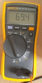
 voltage after adj & 45min R.jpg35.7 KB · Views: 67
 -
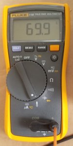
 voltage after adj & 45min L.jpg57.6 KB · Views: 80
 -
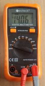
 ini voltage R.jpg78.5 KB · Views: 283
 -
 ini voltage L.jpg87.9 KB · Views: 307
 -
 power up.jpg113.7 KB · Views: 320
 -
 finished.jpg119.5 KB · Views: 308
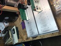
099 is up and playing music. Got the back panel all wrong right input on the left and the switch upside down. Not used to having those things marked. All fixed now.
Also dd not quite understand why 6L6 installed the front panel first in the build guide, my way seemed alot easier until I tried to install the front panel.
Looks wonderful
Also dd not quite understand why 6L6 installed the front panel first in the build guide, my way seemed alot easier until I tried to install the front panel.
Looks wonderful
change to thin mica & goop, for better sleep
But it was hand tightened by our master!
Last edited:
So 10,000 uF + 470 uF + 0.33 uF seems like a good combination.
Thanks for two good answers. I wonder if a 470uF cap can sound so much better than a 10000uF. Will I notice it is even there? I could understand if I had a Mundorf Silver Gold in there, but another large electrolytic. Hm.

Good to see more VFET’s being born!
Nice work Fellas
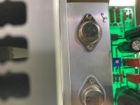
Device temperature has been brought up a few times with the P-channel builds and now N-channel. All amps are essentially the same, I wondered, why has there been a few higher temperature builds? So I mocked up my pair OS sections on the heatsinks. One channel had a slight see-saw action, the other channel felt solid if I tried rocking the OS. I took a close-up pick and you can see a slight space between the T-Bar and heatsink. I checked both surfaces for straightness, the heatsink has a minor wave in it. The wave trough just so happens to be right under the middle of the T-Bar. This situation could be the cause of some devices running hotter than others.
Back in post#58, Monk55 mentioned lapping-in the OS and sinks. Maybe not necessary for all, but definitely worth looking into. My situation looks a bit more involved, probably too much of a void for lapping.
Nice work Fellas
Device temperature has been brought up a few times with the P-channel builds and now N-channel. All amps are essentially the same, I wondered, why has there been a few higher temperature builds? So I mocked up my pair OS sections on the heatsinks. One channel had a slight see-saw action, the other channel felt solid if I tried rocking the OS. I took a close-up pick and you can see a slight space between the T-Bar and heatsink. I checked both surfaces for straightness, the heatsink has a minor wave in it. The wave trough just so happens to be right under the middle of the T-Bar. This situation could be the cause of some devices running hotter than others.
Back in post#58, Monk55 mentioned lapping-in the OS and sinks. Maybe not necessary for all, but definitely worth looking into. My situation looks a bit more involved, probably too much of a void for lapping.
Attachments
I lapped (sanded) my t bars and only the top and bottom edges touched the sanding bar at first. Took a while until I had contact on most of the surface. The middle half inch never touched the sander. I was moving the sander mostly vertical. If some one had a wave like Vunce and a hollow like mine they could be losing a lot of contact. My V-fets just reached 48 C after 1 1/2 hours.
The amp really sounds great. best I can say is it UN-complicates the music. Really wonderful.
The amp really sounds great. best I can say is it UN-complicates the music. Really wonderful.
Great thank you ZM!
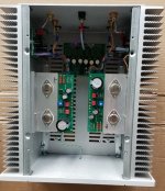
The boards are looking great! Everything is already stuffed appart from the big caps on the output which will be upgraded with some Nichicon KG, and C2 on the front end which will be replace with some Nichicon KZ. And I have to say that I really like the nice finishing touch from the master
Papa's signature is like a little Om

Indeed the heatsinks have “flycutter” head marks. Here you can see after initial block sanding. Also, the T aluminum has ridges. Both should be knocked down with sanding block. Some may be just fine. I took more time to insure they were flat. 8 sq in is not a lot of contact so I wanted it all.
Cheers
Cheers
Attachments
- Home
- Amplifiers
- Pass Labs
- DIY Sony VFET pt 2 (N-Channel Build)