
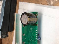
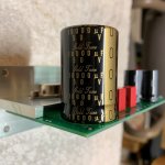
^ Good solution to fitting the larger diameter KG series output cap.
Nice move Monk55
")
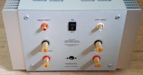
I am also a bit nervous of understanding this switch. This should be VERY clear in a future illustrated build guide.
Just think of it as two separate switches which both have to be on or off at the same time. So you can either use a Double Pole Single Throw (DPST) or simply parallel the two switch locations on the psu board: twist one and three and two and four together and take one pair to each pole of the SPST that comes in the kit.
Have a look at post 135 on page 14 and you will see from Chede's photo that he took the simple route, which may require a thinner wire guage.
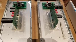
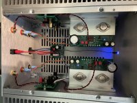
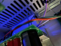
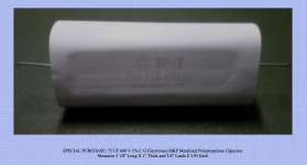
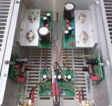
I was fooling around the other day and discovered a nice, inconspicuous way to bypass the large output caps with 75uf of polypropylene for cheap. Apex Jr has quantity of these large axial film caps for less than $4 ea. They fit perfectly under the OS brackets and sound great.
Food for thought. Apex Jr.Home Page
Food for thought. Apex Jr.Home Page
Attachments
How did you come to that value of 75uF?
I have heard other values as well:
I have heard other values as well:
I have done some moderate cap rolling, mostly on the Dreadnought and Bulwark FE boards. I did make one substitution on the original FE board – a 220 uF Elna Silmic in place of the 1000 uF output coupling cap.
The 0.33 uF Wima is a good polypropylene part. It has 5mm lead spacing, which will make it difficult fit alternate components. I’m not inclined to roll this one.
The big 10,000 electrolytic on the OS is a good Rubycon. Best thing here is to keep this and bypass it with a Nichicon KW series 220 uF or 470 uF on the underside of the PCB.
We have a builders thread in place for more discussion.
I was fooling around the other day and discovered a nice, inconspicuous way to bypass the large output caps with 75uf of polypropylene for cheap. Apex Jr has quantity of these large axial film caps for less than $4 ea. They fit perfectly under the OS brackets and sound great.
Food for thought. Apex Jr.Home Page
Is smaller values okay too?
Is smaller values okay too?
Yeah, smaller values are fine.
I could be wrong, but if you take the cap value and the nominal impedance of your speakers, you can calculate a HP roll-off frequency for the bypass cap. Essentially the frequency range the cap would be 'in play.' For instance, with 8 ohm speakers and this 75uf cap, I get a roll-off frequency of 245 hz – meaning I'd expect the cap to have some influence in the range above that frequency (and below to a lesser extent, considering roll-off). I'm positive its more complex than that, but that's how I wrap my brain around it.
That said, if someone who actually knows if thats the case or not could chime in, I'd feel better.
I just bought some second hand 15uF Jantzen Silver Z-cap. With 8ohm speakers, how would that work out? I also have Unknown 100uf, Mundorf 47uf, and 35uF but they are not so nice.
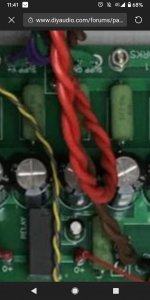
I like how you avoided to take a picture of how you connected the switch. I will continue until I get my visual representation of how this switch is connected, because my mind apparently cannot grasp it.
I like how you avoided to take a picture of how you connected the switch.
I will continue until I get my visual representation of how this switch is connected, because my mind apparently cannot grasp it.- Home
- Amplifiers
- Pass Labs
- DIY Sony VFET pt 2 (N-Channel Build)