@Zen
I have enough of the spec FET for both the P&N channel amps Pop gave us and will be doing those for sure.
I'm not sure where these will go, but was thinking maybe something mono maybe with more ouput. I know Pop has limited his output on First Watt stuff to keep out out of Pass Labs wheelhouse, so I would, most likely, would have towork with others here if I go that route.
I'm not sure where it's going, yet, just through I would toss it out for forum input like yours.
JT
well, I'm certainly glad, whenever I see someone finding some unobtanium
not so because of unobtanium, but because of joy involved, from start and hopefully all the way while building it
do not hurry, in time it'll click and you'll recognize right idea as worthy 158%
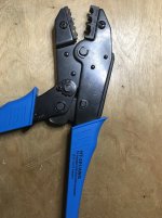
Are those MUNDORF 6.3G Female Blade Connectors?
What tool did you bought to crimp them?
Something of Knipex i guess.
Looks clean. I like it.")
Hi RainfallSky,
naa ... no need for fancy stuff, just standard quality connectors like these:
Security Check
The die-based crimping tool I bought a long time ago, don't know where and how much it cost, but searching online for the inscription yields a number of hits with cost below 15 EUR. I was a bit surprised myself, because I thought I had paid more for it then ... This tool actually works very well - it is a lifetime investment.
After ten years of building amps, I did actually buy myself a Knipex Electronic Super Knips wire cutter ... and I like it very much
Regards, Claas
Attachments

still not working
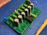
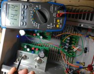
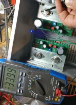
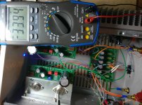
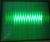
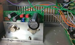
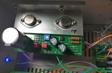
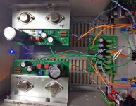
I still have problems with my amplifier. The preamps mesures quite nice, they give nice amplified signal on the input of the output stage. I took some more pictures, of the amp as well as of some measurements. One pictutere of the output signal. Any ideas?
I still have problems with my amplifier. The preamps mesures quite nice, they give nice amplified signal on the input of the output stage. I took some more pictures, of the amp as well as of some measurements. One pictutere of the output signal. Any ideas?
Attachments
-
 250 left.jpg798.4 KB · Views: 129
 -
 82 right.jpg590 KB · Views: 123
 -
 82 links.jpg446.3 KB · Views: 140
 -
 Output.jpg366.8 KB · Views: 177
 -
 Siebung.jpg952.9 KB · Views: 174
 -
 VFet links.jpg839.1 KB · Views: 324
 -
 VFet rechts.jpg1,012.4 KB · Views: 383
 -
 VFet.jpg1,002 KB · Views: 390
 -
 250 right.jpg655.5 KB · Views: 137
awesome job getting those nice and aligned!
For me, the additional challenge is always to prevent solder from creeping up the sides of the spade
... otherwise, I have to scrape / cut it off afterwards with a knife (that works, because the solder is much softer than the material of the spade, or the knife blade).Regards, Claas
Hallo Helmut,
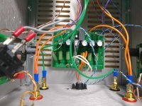
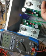
I can't really see how your switch 2 is wired. Have you made sure that the relay engages and that the output does not inadvertently stay shorted when the amplifier is on ?
If it works correctly, you should have a resistance of 1 kOhm between speaker post hot and speaker post ground. Otherwise, and when the amp is off, it should be a short.
Let me compare resistors from your pictures with my build next ...
Regards, Claas
I still have problems with my amplifier. The preamps mesures quite nice, they give nice amplified signal on the input of the output stage. I took some more pictures, of the amp as well as of some measurements. One pictutere of the output signal. Any ideas?
Hi HH,
Since your using the supplied SPST switch, check if your SW2 wiring is engaging the relay?
Whoopsie, Looks like Claas already brought this up. My snail speed messaging strikes again
Last edited:
For me, the additional challenge is always to prevent solder from creeping up the sides of the spade
Regards, Claas
Yes, that’s a good point. I’ve been soldering them from the top of the board more and more.
... and now, please excuse me, I must listen to some music ...
Enjoy
 Bravo ! Applause
I still have problems with my amplifier.. Any ideas?
Do you make with crimping tool strong pressure on the wires with spades who are connected to the speakers outputs ?
Try verify....with continuity tests if all wires have good connection between pcb and speakers outputs ?
I can't see spades in PL products

Okay, I recant the beard comment. When I build one, I'm not changing, there's snot!
a quick connect anywhere in, on, or near the amp. Pop and Wayne look at every point of failure with an eye toward not having a conversation with one a world away as to why the amp failed. That's why you won't find that stuff in the box.
Hey great, you want to swap thenfine,but when you build one you don't for real, FQC&S.
Last edited:
The trimpot is temporary so I can “dial in” the LED brightness. Then measure and replace with fixed resistor.
Hi Vunce,
Could you please let me know the part# for those temporary female connectors which the trimpot is sitting on?
- Home
- Amplifiers
- Pass Labs
- DIY Sony VFET pt 2 (N-Channel Build)