if you got them in kit,, don't fret
if you're building from scratch, same procedure as building any JFet buffer
for same sex JFet buffer, matching of upper vs. lower JFet is not so important - spread is allowed (if DC output offset need to be taken care of, upper source trimpot is solution)
for complementary buffer, especially if used as here - without source resistors (either fixed or as trimpot), they need to be closely matched, if we want predictable performance
The snubber is snubbing as it should, damping a resonance from the transformer.the really Thinking Trap for Greedy Boyz are C4&R6
Though, in my case, the snubber is a bit too narrow (to high-Q). Had the amp on the oscilloscope with a frequency sweep yesterday evening, and I get remnants of the resonance below (30-50 kHz) the snubber's frequency and above as well, showing as some slightly higher gain at those frequencies. Sorry, didn't shoot photos from my scope screen yesterday night. 1 kHz and especially 10 kHz square waves do look somewhat ugly.
That said, I have replaced C2 on the front end by 220 uF Nichicon UES, and I don't know enough about transformers and reflected impedances and such to assess if this substitution would alter the resonant behaviour of the Edcor. Maybe someone with a standard C2 is doing a frequency sweep as well ?
Hope to listen to the amp tonight,
best regards,
Claas
220 uF for the coupling cap is still plenty. The Nichicon UES series cap woul be a good choice as long as it has sufficient voltage rating (>35V).
Recall that the Edcor transformer has an impedance ratio of 25, and that the OS has an input impedance of about 110k. So 110k / 25 is the impedance that the buffer drives at the primary side of the transformer.
Recall that the Edcor transformer has an impedance ratio of 25, and that the OS has an input impedance of about 110k. So 110k / 25 is the impedance that the buffer drives at the primary side of the transformer.
Well, I thought of 600R primary impedance of Edcor. That would give an f3 of 1.2 Hz for C2 = 220 uF.
I think you get a higher cut-off at the ingress of the power board, with C4 / R8 + P1. That would give approx. 4.4 Hz cut-off.
But then, there is always the low-frequency performance of the transformer ... if I sweep a sine below 10 Hz, the output waveform looks "interesting". From RCA in to speaker out, I get a lower - 3dB frequency of rougly 6.5 Hz through the whole amp. But at that frequency, the output looks nothing like a sine wave, and with lots of phase shift. I guess the low-frequency performance is dominated much more by the transformer than by the capacitor couplings.
I'll have to dig through my files for my measurements of my M2. I think it measured only a little better.
Regards, Claas
Recall that the Edcor transformer has an impedance ratio of 25, and that the OS has an input impedance of about 110k. So 110k / 25 is the impedance that the buffer drives at the primary side of the transformer.
Thanks ! That helps me in calculating in the future. Had written my previous post before reading your reply ... So I get a corner frequency of about 0.16 Hz.
Regards, Claas
Some M2x builders prefer the sonic results when the Edcor transformer primary is driven by a Front End ("Norwood") whose output impedance is less than 0.1 ohms. Other M2x builders like the sound they get when the Edcor transformer primary is driven by a different Front End ("IPS6") with a transconductance design, whose output impedance is greater than 1K ohms. Leading to the conclusion that Front End output impedance is poorly correlated to listening results, when using an Edcor transformer for interstage gain.
In the VFET universe there is also the possibility of plugging in and listening to a transformerless Front End card. No Edcor. No Zobel network. No possibility of iron hysteresis. And so forth. Does removing the Edcor, improve the sound? Or is a free-from-Edcor VFET amp less exciting? You can try the experiment and see for yourself.
Scourge, Bulwark, Marauder, Dreadnought "front end" cards for DIY VFET amp
220 uF for the coupling cap is still plenty. The Nichicon UES series cap woul be a good choice as long as it has sufficient voltage rating (>35V)
I didn’t thought that there was any big voltage between the jfets and the transformer and that a 16v cap is plenty enough at that position. Do we really need 35v + for C2 on the front end board ?
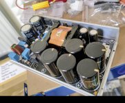
Trying out this supply from MicoAudio…will report back.
What’s the model# of this MicroAudio smps?
It looks to be in the process of being built.
New model from Sami?
Last edited:
what are the right orientation of edcor pc600/15k ?
there isn't pin number...
The pins are slightly offset, hence it will only drop in one way.
If I wanted to try a different mfg of the transformer, the main spec to look for is the 600->15k conversion? Should I be looking for that exactly or will any 1:5 turn ratio do? I'm looking at lundahl since I've used them before.
I know the pinouts will likely be different than the edcor.
Not going to try it for awhile, just mulling over options.
I know the pinouts will likely be different than the edcor.
Not going to try it for awhile, just mulling over options.
A few diyAudio members have built and posted "clones" of First Watt's transformer amplifiers, including PCB footprint options to drop in and try several different transformers. Their boards generally include footprints for some, or all, of: Jensen, Edcor, Lundahl, Cinemag, Hammond, Sowter, and AudioNote.
You want a transformer with good properties, such as
You want a transformer with good properties, such as
- output (secondary) is able to drive the load you connect to it
- input (primary) is easily driveable by the circuits you connect to it
- turns ratio is in the range you seek
- very low -3dB frequency of LF roll off (ideally < 1 Hz)
- very high -3db frequency of HF roll off (ideally > 80 kHz)
- transformer's max RMS voltage spec is well below your circuit's level @ clipping
You may determine this by asking yourself the following questions:I didn’t thought that there was any big voltage between the jfets and the transformer and that a 16v cap is plenty enough at that position. Do we really need 35v + for C2 on the front end board ?
What is the DC offset across the Edcor primary winding when the amp is first turned on?
What is the DC offset across the primary winding while the amplifier is operating?
What is the DC offset on the output of the JFet buffer?
Remember that the VFET amp runs from a single 36V rail, not +/– 22V like the M2
Looking forward to your pics.
Rafa.
I doubt whether there's anything to warrant yet more pics of the same amp.
(And for an ancient Brit I'm afraid a Test Match at Lords takes precedence.)
- Home
- Amplifiers
- Pass Labs
- DIY Sony VFET pt 2 (N-Channel Build)