If you have other resistors you may be able to parallel/series connect some resistors to achieve 10k and get your amp running. Since R8 is in series with a 50k pot you don't need exactly 10k.
For instance 16k paralleled with 27k is 10k. Or a combination of other resistors that you have may also give you 10k.
For instance 16k paralleled with 27k is 10k. Or a combination of other resistors that you have may also give you 10k.
You said that you received 10k, then you said you received 27k, which you then edited to 10k, and now you confirm that you received 10k.
As I said previously, the latest schematic and BOM that I referenced in my post #256 show R8 as 10k. Since it is the latest and since you also received 10k resistors, I would have to assume it is correct.
By the way, I just checked the diyAudio Store page for the amplifier kit and when I clicked on "Article / Bill of Materials" it went to the web page that I referenced in my post #256.
Last edited:
Right, Ben, but I explained that I made a mistake because I have job and was at work. I can’t be researching my audio stuff when I’m required to be working. When I realized I made the mistake as you noted it was because I was at my work and not at home where the parts are. I corrected and flipped values to what I actually received and what the BOM I have from the NP Sony Vfet P channel build from the first lottery.
That BOM is taken directly from the first Vfet lotery P channel build.
So back to my original question.
Is the 27k resistors from the original first lottery P channel build now superseded with 10k resistors?
If so then I’m good to go, but I don’t want to be guessing and then have something go wrong.
Now I am extremely confused. Which amplifier do you have? The lottery P channel or the OS2 P channel?
If you have the OS2 P channel amp, follow the latest OS2 schematic and BOM. If you have the lottery P Channel amp, follow the BOM for the lottery P channel.
Also when I checked the OS2 kit website on the diyAudio Store, it went to the OS2 Article and BOM, not to the lottery article or BOM.
https://diyaudiostore.com/collections/diy-sony-vfet/products/vfetless-round-3-output-stage
Ben, here’s the link from the 6l6 build thread.
https://guides.diyaudio.com/Guide/Sony+Vfet+(P+2021)/15?lang=en
That’s where I got the schematic (down by step 4) from and it shows 27k for R8 not 10k.
https://guides.diyaudio.com/Guide/Sony+Vfet+(P+2021)/15?lang=en
That’s where I got the schematic (down by step 4) from and it shows 27k for R8 not 10k.
Benjisan,
This is the doc for the current store offering:
https://www.diyaudio.com/community/attachments/diy-sony-vfet-amplifier-os2-pdf.1035400/
This is the doc for the current store offering:
https://www.diyaudio.com/community/attachments/diy-sony-vfet-amplifier-os2-pdf.1035400/
Hi Vunce and Dennis,
Yes, I understand what Ben Mah is conveying, but as I stated the package of resistors I received in the P channel kit I just purchased had a white label attached to it with a web link for the resources to build the round 3 P-channel Vfet was 404.
There was no BOM included with the parts I received other than the information on that white tag that was included with the current DIY kit the store sold me.
I believe the link Ben Mah provided was for the build of the round 2 DIY Sony VFET OS2 output which is N type build and not the P type build that I’m assembling.
If that resistor value of 10k is okay for my build; and not the 27k listed for the previous P channel build, then everything is okay but I’m not hearing from anybody who can actually verify this for me.
Okay, I see where the 10k is now the resistor of choice instead of the 27k one from the build guide.
We will go with the 10k and consider this just some unessesary confusion on my part since the dead web link from the label on the package of resistors, the 6l6 build guide showing the 27k resistor, and lack of a printed BOM was the source of confusion for me.
Thanks everyone for all the replies.
We will go with the 10k and consider this just some unessesary confusion on my part since the dead web link from the label on the package of resistors, the 6l6 build guide showing the 27k resistor, and lack of a printed BOM was the source of confusion for me.
Thanks everyone for all the replies.
Thanks Vunce. The store's product page for these round 3 output stages has a link to the BOM for this product. However, improving the consistency of BOM information and having each page list the exact BOM, as well as a history of revisions and what changed, is a high priority on the store's todo list and should be completed later this year as part of a store improvements initiative.
.....................
I believe the link Ben Mah provided was for the build of the round 2 DIY Sony VFET OS2 output which is N type build and not the P type build that I’m assembling.
If that resistor value of 10k is okay for my build; and not the 27k listed for the previous P channel build, then everything is okay but I’m not hearing from anybody who can actually verify this for me.
No mistake. OS2 is the non-lottery third round of VFET amplifiers that includes N and P channels. And as I said before, R8 is 10k for P channel OS2.
")
Last edited:
Benjisan,
Please look at Nelson's project document I linked to in post #268 above. It shows the schematics and parts list of the P-channel kit you have (as well as the N-channel version). The schematics/parts list in the build guide you looked at are for the P-channel Lottery Vfet amp offered last year, which is different from (but similar to) what you have purchased.
Please look at Nelson's project document I linked to in post #268 above. It shows the schematics and parts list of the P-channel kit you have (as well as the N-channel version). The schematics/parts list in the build guide you looked at are for the P-channel Lottery Vfet amp offered last year, which is different from (but similar to) what you have purchased.
Hi Dennis,
Yes, I got the document you linked and also the one from Ben Mah.
I just wanted more clarification since the white label attached to my parts bag that stated for all information go to the firstwatt.com web link and the Pass Labs forum, in which I did.
The confusion I brought up with regards to the 27K resistor and the 10k resistor was from the web link on the parts bag being DOA = 404. I was just trying to make sure (clarification) that's why I was asking if the 27k resistor was superseded by the 10k resistor.
Jason has already acknowledged there was a slight information anomaly in the works and will be taking steps to address it.
So everything on my end is good now.
Thank you, and to all the guys who jumped in and helped clear things up for me.
Sorry about the delay, sometimes life gets in the way of audio...
10K is the correct value, and is also specified on my schematics and BOM in the article unless I am mistaken.
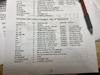
Actually, I don't know where the BOM in your picture came from unless it was some early copy.
In any case, 27K would have worked fine also.

10K is the correct value, and is also specified on my schematics and BOM in the article unless I am mistaken.
Actually, I don't know where the BOM in your picture came from unless it was some early copy.
In any case, 27K would have worked fine also.
Hi Class,Yep - and I think that is where the confusion came from ... DIY VFET part 1 was using 2SJ28 and had R8 = 27 kOhm, and in the "OS2" output stage in the VFET part 3 series, in the P channel version for the single-die 2SJ18, R8 = 10 kOhm.
Regards, Claas
I’m using the P-channel 2SJ28 Vfets and not the 2SJ18.
Mr. Pass said that the resistor value either being 10k or 27k wouldn’t matter.
But that makes me want to ask another question.
First off take it easy on me since I’m not versed in any electronics formally, but what is the 10k or the 27k resistor for that matter R8 actually doing/controlling in its placement with regards to the circuit?
Layman terms for me as I’m just trying to learn fellas.
- Home
- Amplifiers
- Pass Labs
- DIY SONY VFETS pt 3 - Got VFETs?