I am not fully versed in DRC yet, but here goes nothing... perhaps will be backed up by others.
Right now, I am attempting a single listening position.
I know the other commercial products ask you to do plenty of measurements and they average those readings to create an average filter.
Since in REW, it is possible to average the responses, maybe it would be possible to take a few measurements, average all of them in REW, and export that to DRC Designer?
I'm having more success in a more controlled environment.
In my attempts to discover where the double peaks origin, I moved one W8-1772 speaker cabinet upstairs, to the better and smaller room. It's a classroom / recording room.
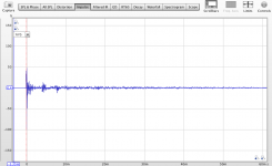
Made a couple sweeps in REW to confirm that the double peaks do not come from the speaker themselves. To my relief, it wasn't. I had a much nicer impulse there.
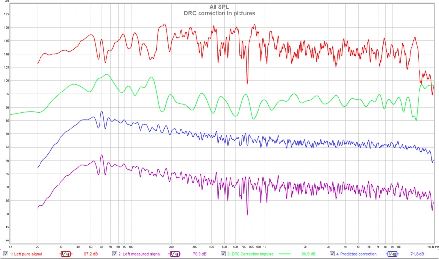
Here's the before (blue) and after (red) convolution of the W8 in that room. As you can see, it worked, and you can imagine that it sounded pretty good too.
So, I'm happy to say that I have progressed.
There is a matter in the impulse still, I have a wobble at the start of the impulse (hard to see zoomed out, but clearly there when zoomed in). I am not sure if it comes from the W8 construction (having a whizzer cone, or being an 8" compared to a 3") or something else.
In my attempts to discover where the double peaks origin, I moved one W8-1772 speaker cabinet upstairs, to the better and smaller room. It's a classroom / recording room.
Made a couple sweeps in REW to confirm that the double peaks do not come from the speaker themselves. To my relief, it wasn't. I had a much nicer impulse there.
Here's the before (blue) and after (red) convolution of the W8 in that room. As you can see, it worked, and you can imagine that it sounded pretty good too.
So, I'm happy to say that I have progressed.
There is a matter in the impulse still, I have a wobble at the start of the impulse (hard to see zoomed out, but clearly there when zoomed in). I am not sure if it comes from the W8 construction (having a whizzer cone, or being an 8" compared to a 3") or something else.
Attachments
Er... a little late, and sorry for a very basic question:
It's for a single listening position, right?
If not, what kind of area can it cover?
Or, another way to ask: if it's well-tuned for one position, how much would it change at other positions in the room?
A legitimate question, one that was bothering me before I started with DRC. It's true the DRC procedure calls for a single listening position to correct the impulse. You have to keep in mind that the time frame in which it corrects the response is actually very short in higher frequencies. Similar to correcting with EQ for a gated measurement but a shorter gate than most would use.
The "Normal" template corrects only 0.50 ms at 20 KHz and is considered quite long by many using DRC. Gmad corrects 4 cycles from 20 Hz to 20 KHz and has great results. 4 cycles at 20 KHz is just 0.20 ms
What you need to get satisfying sound depends a lot on what speaker you are correcting.
After correcting my speaker I made measurements ranging from 1 m to the left to 1 m to the right of the microphone.

After averaging those measurements was actually quite close to the single point measurement:

To compare here are the curves I played with prior to the above measurement:

I stuck with the light green curve at that time. Adding more damping to my room changed my preferences later to a less steep curve but that's another story.
As you see the average from my couch and my single point target are not that far apart. And I'm not the only one trying that, I've seen measurements from user mitchba indicating the same behaviour. See his post here:
http://www.diyaudio.com/forums/multi-way/271119-smooth-flat-vs-accurate-hi-fidelity-9.html#post4261806
He's using Acourate but the basic principles are the same. More info and background from Mitch can be found here: Computer Audiophile - Advanced Acourate Digital XO Time Alignment Driver Linearization Walkthrough
During the development of DRC the author of Acourate and DRC were in contact as can be seen on the DRC forums as well as in the DRC documentation. Acourate has some advanced filtering that might lead to even better results but comes at a higher price.
Personally I have played with the window settings and listened to what it did for my arrays. The arrays are a different animal than a single speaker because they have a time smear of frequencies arriving at that single microphone position. Based on time arrival in distance to the microphone the up most speaker arrives about 50 ms behind the center one right in front of the microphone. That means I need a setting close to the "Normal" window to shape my high frequencies, but in the mid frequencies I'd need less cycles because 50 ms there is way shorter compared to the actual wave lengths.
If I correct using the normal template I get focussed sound on my listening position. But if I move a bit to the left (more than about 30 cm) or right the image snaps to the closest speaker.
But if I use a custom template, using the same 50 ms at 20 KHz but less than the 10 ms the normal template dictates at 1 KHz I can move more than 50 cm and keep the image right in front of me. As you can imagine I'm still playing with the windowing to get optimal results.
So we can't predict what it will do for other speakers without trying.
Sorry for the lengthy response but I hope it somewhat answers your question. After my own experience with the averaging of the multiple measurements I'm no longer worried about that single point measurement.
I'm having more success in a more controlled environment.
In my attempts to discover where the double peaks origin, I moved one W8-1772 speaker cabinet upstairs, to the better and smaller room. It's a classroom / recording room.
Made a couple sweeps in REW to confirm that the double peaks do not come from the speaker themselves. To my relief, it wasn't. I had a much nicer impulse there.
Here's the before (blue) and after (red) convolution of the W8 in that room. As you can see, it worked, and you can imagine that it sounded pretty good too.
So, I'm happy to say that I have progressed..
Good progress! I hope we'll find the reason why your other room is so difficult to correct. I've seen plots from you indicating the second peak is even higher than the first. I cannot imagine this would be caused by reflections.
There is a matter in the impulse still, I have a wobble at the start of the impulse (hard to see zoomed out, but clearly there when zoomed in). I am not sure if it comes from the W8 construction (having a whizzer cone, or being an 8" compared to a 3") or something else.
It can be a number of things but that Whizzer cone is high on my list of suspects. What does the inside of your speaker look like? Does it have lining like felt on the inside walls? It wouldn't explain the wiggle before the main peak but anything we can do to better the impulse, the less DRC has to correct.
Last edited:
Wesayso, amazing reply to CLS and exactly the kind of information I hoped to gather when I started this thread. Thank you!
About the W8 cabinets, I had them lined with felt, but over the weekend, after seeing the double peaks, I added some rockwool in the inside corners and some polyfill behind the speaker. It didn't affect the sound, nor the double peaks though.
About the W8 cabinets, I had them lined with felt, but over the weekend, after seeing the double peaks, I added some rockwool in the inside corners and some polyfill behind the speaker. It didn't affect the sound, nor the double peaks though.
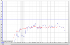
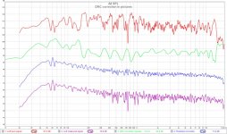
I figure a picture says more than thousand words, let's see a simplified presentation of what DRC actually does.
For this example I used the left channel of my Line Arrays. It does not show everything that's going on but makes it a bit clearer to see what it is doing.
A side note: the imported correction file isn't exactly the same as the file used in the measured signal, but close enough for this example.
From top to bottom:
Rough measurement taken at listening position. (base signal)
Impulse correction from DRC imported into REW (actual correction)
DRC correction applied to the rough measurement (Red signal + Green signal)/2. (predicted response)
Actual measurement of the corrected response at the listening position using convolution. (actual measurement of response)
It shows that it does a lot of corrections to the frequency response that would be very hard to replicate with (P)EQ. This simple graph leaves a lot of the factors out like phase correction etc. but it clearly demonstrates it's power. The "Maximum correction Boost" in this example was high at 9.25 dB. Not recommended for use on a single point source. But I use DRC to shape the response of my 25 driver/side Line Arrays.
It clearly shows there aren't any boosts at small dips taking place, even with this large Maximum correction Boost factor.
Attachments
Last edited:
Regarding audio on PC systems then from Win Vista and up Windows sound system control sample rate locked to whatever user have set for the input and output devices. This can be overruled by having programs with build in WASAPI or ASIO the bit perfect exclusive modes.
Personal experience is when i have to use Windows sound system that manual changing settings for input and output devices regarding sample rate settings gives far best precision instead of letting Windows do SRC in background. This means that when using my USB DATS device set 44.1kHz, if measuring with my USB UMM-6 set 44.1kHz and if measurering with UMIK-1 set 48kHz, and at same in REW need to change settings because the two microphones prefer either 44,1kHz or 48khz. This is a lot of extra work to do before making a program task but for my setup looks clear like getting better repeated precision and flawless operation.
Using JRiver as player i really enjoy WASAPI taking exclusive control and no exstra work is needed") .
.
Perceval use a mix in Windows sound system for REW and WASAPI or ASIO for JRiver. Could there be a chance if before starting up your mission that to manual set Windows controlled input and output devices to same sample rate as the intended task would use, you would get better results.
Personal experience is when i have to use Windows sound system that manual changing settings for input and output devices regarding sample rate settings gives far best precision instead of letting Windows do SRC in background. This means that when using my USB DATS device set 44.1kHz, if measuring with my USB UMM-6 set 44.1kHz and if measurering with UMIK-1 set 48kHz, and at same in REW need to change settings because the two microphones prefer either 44,1kHz or 48khz. This is a lot of extra work to do before making a program task but for my setup looks clear like getting better repeated precision and flawless operation.
Using JRiver as player i really enjoy WASAPI taking exclusive control and no exstra work is needed
.Perceval use a mix in Windows sound system for REW and WASAPI or ASIO for JRiver. Could there be a chance if before starting up your mission that to manual set Windows controlled input and output devices to same sample rate as the intended task would use, you would get better results.
Last edited:
My experiences regarding single position measurements are consistent with those of wesayso. I tend to think of multiple position averaging as a low tech means to achieving frequency dependent time windowing. The size of the listening area in which the correction is valid with DRC depends on the windowing length. I'm happy with the results I get with a windowing length which is still short enough to avoid artifacts from any listening position.
Hi wesayso,
Thanks a lot for the informative and educational post. Your results look excellent to me.
I've been using Behringer DEQ2496 myself. It has an auto EQ function to correct the frequency response (for the location of mic). It uses 31-band graphic EQ for this. I believe there's no correction of phase shift by the room etc. When done, it leaves many adjustments here and there across the whole spectrum, some of them are quite severe.
And if I moved the mic, there'd be a different set of peaks and dips right away by very large amplitudes and by a mere foot, let alone 1 meter.
I don't like the sound by such 'correction'. It sounds clinical, sharp, very "hi-fi" in the initial impression, but soon I feel it unnatural and fatiguing. I've tried several times, it has never satisfied me. I guess it fails in the timing (phase).
The correction by impulse response makes more sense, considering the phase issue. I did a quick browsing on the web site of REW. I saw measurement and EQ, but I didn't find how it corrects the phase shift. I think it does, but how? Sorry if it's been mentioned and I missed.
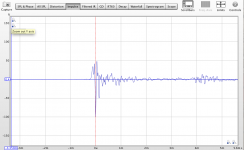
Found the double peak!
After trying a bunch of combination, change amp, isolated the feet of the speakers, etc...
The double peak is caused by a reflection.
Right behind the couch, at 1.3m, there is a staircase with concrete wall. On a hunch, I placed the mic ON the seat of the couch, using the back rest as a shield to the back wall reflection... that worked.
Then, I placed a mic back at ear level, but using a cardiod mic, so it wouldn't listen to the back wall reflection as an omni mic would.
This gave me a much nicer impulse. When comparing right and left, it's almost clean. In stereo, there is a little shift and I'm sure if I moved the mic slightly, they would align.
Pressed for time, I used that to generate a few gentle filters with DRC Designer, which helped the sweeps but still has a lot of work. My room, being a concrete block, has many of those reflections and probably won't be able to get a perfect curve. Also, I feel the sliders for a custom filter are a bit crude, not giving feedback as to what's really happening, so I am thinking to switch to the original DRC software... and learn it!
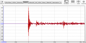
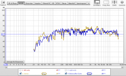
So, here are some new graphs, showing a single speaker impulse and the sweeps, before and after convolution.
Baby steps....
After trying a bunch of combination, change amp, isolated the feet of the speakers, etc...
The double peak is caused by a reflection.
Right behind the couch, at 1.3m, there is a staircase with concrete wall. On a hunch, I placed the mic ON the seat of the couch, using the back rest as a shield to the back wall reflection... that worked.
Then, I placed a mic back at ear level, but using a cardiod mic, so it wouldn't listen to the back wall reflection as an omni mic would.
This gave me a much nicer impulse. When comparing right and left, it's almost clean. In stereo, there is a little shift and I'm sure if I moved the mic slightly, they would align.
Pressed for time, I used that to generate a few gentle filters with DRC Designer, which helped the sweeps but still has a lot of work. My room, being a concrete block, has many of those reflections and probably won't be able to get a perfect curve. Also, I feel the sliders for a custom filter are a bit crude, not giving feedback as to what's really happening, so I am thinking to switch to the original DRC software... and learn it!
So, here are some new graphs, showing a single speaker impulse and the sweeps, before and after convolution.
Baby steps....
Attachments
Hi wesayso,
Thanks a lot for the informative and educational post. Your results look excellent to me.
I've been using Behringer DEQ2496 myself. It has an auto EQ function to correct the frequency response (for the location of mic). It uses 31-band graphic EQ for this. I believe there's no correction of phase shift by the room etc. When done, it leaves many adjustments here and there across the whole spectrum, some of them are quite severe.
And if I moved the mic, there'd be a different set of peaks and dips right away by very large amplitudes and by a mere foot, let alone 1 meter.
I don't like the sound by such 'correction'. It sounds clinical, sharp, very "hi-fi" in the initial impression, but soon I feel it unnatural and fatiguing. I've tried several times, it has never satisfied me. I guess it fails in the timing (phase).
The correction by impulse response makes more sense, considering the phase issue. I did a quick browsing on the web site of REW. I saw measurement and EQ, but I didn't find how it corrects the phase shift. I think it does, but how? Sorry if it's been mentioned and I missed.
My experiences with auto EQ have never been good. I had it on my Pioneer radio in the car. Never tried it on my DEQ2496 though.
I don't know what the DEQ does internally but I bet you could get better results gently waving the microphone within your listening area while running auto EQ?
REW's auto EQ does consider phase response in it's generation/prediction.
But from what I tried (I ran it and used the PEQ settings it provided) it was way to eager to fill all dips. Afterwards I looked at the results and once I softened up all narrow EQ suggestions (by deletion of that filter while trying to stay true to the general target) it sounded much better.
REW is only used as the measurement suite in this thread. The actual impulse correction is done by the free (under the terms of the GNU General Public License) DRC-FIR from Denis Sbragion. I consider it a very powerful tool, I'd say more powerful than most Auto EQ solutions available.
You can still run into the same problems with DRC (or I suppose any other correction program) with the wrong settings. Shorter windows gives a more pleasing sound in a wider area. Yet I had to make my window in high frequencies longer to retain focus in the center of my image.
It wasn't until I shortened the mid frequency windowing that I got rid of the strained sound the longer windows caused to the overall sound. I try to use as short a window as possible while keeping the benefits of the correction at maximum.
I guess it's always a balancing act. DRC actually corrects the phase of the first (windowed) wave front. Tiny changes in settings can make huge differences.
Number one for me is the timbre of the sound. The room plays a large role to get that right. Imaging is more a factor of equal balancing of left and right channel and my guess is if you get that right for both frequency and phase you get the maximum effect in imaging. Not the phase you see on a 500 ms REW window with all anomalies of the room in it. Phase can act as a steering mechanism for the sound and with the left and right channel having equal phase response in the first wave front it maximises what stereo can do I.M.H.O.
Last edited:
Found the double peak!
After trying a bunch of combination, change amp, isolated the feet of the speakers, etc...
The double peak is caused by a reflection.
Right behind the couch, at 1.3m, there is a staircase with concrete wall. On a hunch, I placed the mic ON the seat of the couch, using the back rest as a shield to the back wall reflection... that worked.
Then, I placed a mic back at ear level, but using a cardiod mic, so it wouldn't listen to the back wall reflection as an omni mic would.
This gave me a much nicer impulse. When comparing right and left, it's almost clean. In stereo, there is a little shift and I'm sure if I moved the mic slightly, they would align.
Pressed for time, I used that to generate a few gentle filters with DRC Designer, which helped the sweeps but still has a lot of work. My room, being a concrete block, has many of those reflections and probably won't be able to get a perfect curve. Also, I feel the sliders for a custom filter are a bit crude, not giving feedback as to what's really happening, so I am thinking to switch to the original DRC software... and learn it!
So, here are some new graphs, showing a single speaker impulse and the sweeps, before and after convolution.
Baby steps....
My oh my! Never have I seen that loud a reflection before. Still it puzzles me that it wasn't seen in your first uploaded file in the left and right channel. It was there in the stereo measurement though. Not sure what happened there...
To understand the custom DRC Designer settings you can look at the variables it ads to the generated batch files. That's how I play with it. Tiny setting changes can make quite a big difference. The difference between the Normal and the Soft template can be seen. Only windowing and boost factor differ between those two. Eventually it will be better to use DCR as is but it requires more tools or scripts to get everything done. I'm working around DRC Designer by using a custom template as base. It always uses the Soft template so I put my own version there. That way I can easily play with windowing settings using DRC Designer.
Go over the documentation of DRC to get an idea of what does what. It's actually quite scary as there are way to many settings to play with.
.....
Afterwards I looked at the results and once I softened up all narrow EQ suggestions (by deletion of that filter while trying to stay true to the general target) it sounded much better.
....
Thanks for sharing.
I've been doing the similar thing in DEQ and having similar feels of the effects.
I'll look into Denis Sbragion's site.
Thanks for sharing.
I've been doing the similar thing in DEQ and having similar feels of the effects.
I'll look into Denis Sbragion's site.
The documentation on that site is enough for many sleepless nights of reading!
A gentler approach would be with DRC Designer, but the original site is good info to see what the software is doing... a lot!
I am really trying to like JRiver, but it doesn't like me!
I wanted to watch a program in surround last night, so, I deactivated the convolution, put back my EQ mode, changed the device from WASAPI to Asio and selected 5.1 surround.... BUT ... JRiver is not sending any audio to the center, surrounds or sub channels anymore.
I tried to quit the program, reboot Windows... nothing I do will let me have anything else than L/R stereo.
I think I will move back to a Mac.
I had a good thing going with a Mac, and I can apply the convolution filter easily in my setup. I like VLC or mPlayer enough, they are better at handling Chinese subs for my wife (JRiver's support of Chinese characters is horrible). Most importantly, the AudioBox drivers for Mac are much better than the PC version. I still hear pops and clicks when I do a sweep with REW on the PC side, and that PC has been optimised for audio duty, following the settings used in recording stations.
I use AU Lab, which lets me route all the computer's audio through it (kinda like the LoopBack mode in JRiver). Along with SoundFlower, I can have all my surround channels, mix to buses and aux, add Hi/LowPass filters, and add the DRC filter using LAConvolver... even better, I will probably be able to apply DRC to my center channel as well, which would sound killer up front. I'll probably leave the surrounds alone... for now
The only problem will be to generate the filters with DRC designer. I tried using Wine and a CrossOver demo, but that didn't work. I'll give Fusion a shot, otherwise, it will mean that I will have to turn off the Mac and boot into Windows to generate filters, then off and boot to the Mac again.
Did you check Output Format under DSP Studio? Perhaps that one is still on 2 channels?
But if you feel more comfortable on the Mac I'd say stick with that. It's kinda rough having to reboot for filter generation though. No cheap windows Laptop in the house that could do it? I confiscated my son's old laptop many times for different tasks like getting impedance readings.
But if you feel more comfortable on the Mac I'd say stick with that. It's kinda rough having to reboot for filter generation though. No cheap windows Laptop in the house that could do it? I confiscated my son's old laptop many times for different tasks like getting impedance readings.
Yep, I did try 2.1 and 5.1 in the Output Format, but nothing changed. Really weird.
I got DRC Designer to work with CrossOver. I had forgot to tell the app where it was located, so it could find its files. Tried with Wine again, but still no joy.
At least CrossOver is working, but you are right. There's an old laptop (my sister-in-law's old one) I could "commandeer" for filter generation duties. That'd be great!
We're in business!
Quick question, when you mentioned the files to look at the batch files from DRC designer, was it something like: drcOutputRight44100custom.txt ?
This is what I get (don't mind the numbers, it was a bogus filter to see if it worked), but I don't see where the time window fits into this???
Code:
Final allpass convolution...
MP signal minimum phase dip limiting...
Allocating homomorphic deconvolution arrays.
MP Recover homomorphic deconvolution stage...
Minimum phase component final windowing.
Allocating minimum phase EP recovering arrays.
Minimum phase EP recovering...
Allocating excess phase component prefiltering array.
Excess phase component single side sliding lowpass prefiltering.
Input signal prewindowing.
R - Initial lowpass convolution...
R - Band:   0,    20.0 Hz, width:    872, FIR, convolution...
R - Band:   1,    25.2 Hz, width:    778, FIR, convolution...
R - Band:   2,    31.8 Hz, width:    685, FIR, convolution...
R - Band:   3,    40.1 Hz, width:    597, FIR, convolution...
R - Band:   4,    50.4 Hz, width:    515, FIR, convolution...
R - Band:   5,    63.6 Hz, width:    440, FIR, convolution...
R - Band:   6,    80.1 Hz, width:    373, FIR, convolution...
R - Band:   7,   101.1 Hz, width:    314, FIR, convolution...
R - Band:   8,   127.1 Hz, width:    264, FIR, convolution...
R - Band:   9,   160.2 Hz, width:    221, FIR, convolution...
R - Band:  10,   202.0 Hz, width:    185, FIR, convolution...
R - Band:  11,   254.9 Hz, width:    155, FIR, convolution...
R - Band:  12,   322.8 Hz, width:    130, FIR, convolution...
R - Band:  13,   407.0 Hz, width:    110, FIR, convolution...
R - Band:  14,   511.3 Hz, width:     94, FIR, convolution...
R - Band:  15,   642.6 Hz, width:     81, FIR, convolution...
R - Band:  16,   817.5 Hz, width:     70, FIR, convolution...
R - Band:  17,  1016.4 Hz, width:     62, FIR, convolution...
R - Band:  18,  1288.0 Hz, width:     55, FIR, convolution...
R - Band:  19,  1666.7 Hz, width:     49, FIR, convolution...
R - Band:  20,  2069.8 Hz, width:     45, FIR, convolution...
R - Band:  21,  2726.0 Hz, width:     41, FIR, convolution...
R - Band:  22,  3237.2 Hz, width:     39, FIR, convolution...
R - Band:  23,  4498.6 Hz, width:     36, FIR, convolution...
R - Band:  24,  5168.4 Hz, width:     35, FIR, convolution...
R - Band:  25,  7353.8 Hz, width:     33, FIR, convolution...
R - Band:  26,  9320.7 Hz, width:     32, FIR, convolution...
R - Band:  27, 12718.4 Hz, width:     31, FIR, convolution...
F - Band: 28, 20000.0 Hz, width: 30, FIR, completed.That's the actual DRC process, not the variables.
When running custom settings in DRC Designer look at the file: drcWrapperRunDRCRightcustom_44100.bat
That one contains the actual varables that DRC Designer is giving DRC to generate the filter.
Here's one of mine:
In this file you can see I chose a long upper frequency window but bringing down the EPWindowExponent variable to 0.88 instead of the usual 1.0 makes the window at say 1000 Hz way shorter. It could work for you to, seeing how the impulse is a bit time smeared in high frequencies due to the whizzer cone.
With these settings I have an even longer window than the Normal template at 20.000 Hz but shorter than the Normal template at 1000 Hz.
I took that wisdom from the multiple WE graphs in DRC's documentation:
As an example, if you like the tight imaging from the Normal template but the overall sound of the Soft template all you'd need to do is move the left top slider to 22% (EPUpperWindow=44) and the middle one to about 25% (EPWindowExponent=0.88) And leave the bass slider low as in the Soft preset (MPLowerWindow=33116).
You could raise the Maximum Correction Boost to 6.02 dB... play with it a little based on what you think/feel of the standard settings of Normal and Soft.
Move a bit from side to side while listening. Does the image stay focussed? Just something that worked very well for me, your case may be different.
But before all that, make sure you have clean measurements to start with!
When running custom settings in DRC Designer look at the file: drcWrapperRunDRCRightcustom_44100.bat
That one contains the actual varables that DRC Designer is giving DRC to generate the filter.
Here's one of mine:
Code:
cd C:\DRCDesigner\drc-3.2.0\sample
drc.exe --MCFilterType=M --MCPointsFile="C:\DRCDesigner\drc-3.2.0\source\mic\151113-ECM8000-D1302067118-corrected.cal" --PSPointsFile="C:\DRCDesigner\drc-3.2.0\sample\DRCDesignerCustomizedPoints.txt" --BCInFile=RightSpeakerImpulseResponse44100.pcm --PSOutFile=RightSpeaker44100CUSTOM_12.pcm --BCImpulseCenterMode=M --BCImpulseCenter=44100 --BCInitWindow=131072 --EPLowerWindow=1600 --EPPFFinalWindow=1600 --EPUpperWindow=54 --EPWindowExponent=0.88 --ISPELowerWindow=800 --ISPEUpperWindow=600 --MPLowerWindow=38400 --MPPFFinalWindow=38400 --MPUpperWindow=54 --MPWindowExponent=0.88 --MSFilterDelay=800 --PLMaxGain=2.8 --RTLowerWindow=32768 --RTOutWindow=38400 --RTUpperWindow=54 --RTWindowExponent=0.88 --RTWindowGap=54 soft44100.drc
move /y RightSpeaker44100CUSTOM_12.pcm "C:\DRCDesigner\ConvolverFilters"
In this file you can see I chose a long upper frequency window but bringing down the EPWindowExponent variable to 0.88 instead of the usual 1.0 makes the window at say 1000 Hz way shorter. It could work for you to, seeing how the impulse is a bit time smeared in high frequencies due to the whizzer cone.
With these settings I have an even longer window than the Normal template at 20.000 Hz but shorter than the Normal template at 1000 Hz.
I took that wisdom from the multiple WE graphs in DRC's documentation:
Here you can see that varying the WE variable (middle slider in DRC Designer) can change the effect on the mid frequencies quite a bit.
As an example, if you like the tight imaging from the Normal template but the overall sound of the Soft template all you'd need to do is move the left top slider to 22% (EPUpperWindow=44) and the middle one to about 25% (EPWindowExponent=0.88) And leave the bass slider low as in the Soft preset (MPLowerWindow=33116).
You could raise the Maximum Correction Boost to 6.02 dB... play with it a little based on what you think/feel of the standard settings of Normal and Soft.
Move a bit from side to side while listening. Does the image stay focussed? Just something that worked very well for me, your case may be different.
But before all that, make sure you have clean measurements to start with!
Attachments
Last edited:
- Status
- This old topic is closed. If you want to reopen this topic, contact a moderator using the "Report Post" button.
- Home
- Loudspeakers
- Full Range
- DRC - trials, failures and successes