I still can not understand why this is happening, because it is a good, low noise, low PSRR voltage converter. Why exactly does an op amp work well there? And did it mean that in the VCCA, DVCC, Clock ADM lines would work too badly?
Audio circuits such as for opamps seem to need low power supply output impedance up to maybe 100kHz or so. Also, opamp supplies and shunt regulators can regulate voltage down in addition to regulating it up.
LDO's can typically can only regulate voltage up, as one factor. If there is ringing in loads, or maybe some other regurgitation of current from current output dac switching, etc., then there might be some benefit to downward regulation. Hard to say for sure what it is with audio that doesn't work well with some supplies. Haven't tried to study it myself and haven't read an accounting of it that I find fully satisfying from a technical perspective. However, that enough uf of parallel film caps often turn out to be very helpful is probably a big hint as to what to look for.
An interesting audio voltage regulator study was published in Linear Audio magazine. They performed a number of measurements and did some listening tests. Unfortunately, a couple of the best rated 3-terminal regulators according to the article no longer seem to be available. That being said, New Class D was maybe third best 3-terminal type they tested (based on my quick read, IIRC) which was why I decided to try that one. I have to say for an off-the-shelf regulator, I liked the sound a lot when I tried it (enough so that I want to try some more of them for other uses and see how well I like them for other applications).
Regarding digital circuits and LDOs, they seem to work fine with LDOs. In fact that's what LDOs are typically marketed for: RF circuits, clocks, digital circuits, etc.
There is one more spot for soldering a smaller oscillator. What do you think, is it worth removing it, leaving only the necessary?
Should be okay to remove it or leave it. Shouldn't cause any problems to leave it.
Last edited:
I finished replacing the oscillator and turned on the DAC for the first time. I could not believe my ears. The sound really got much better. Particularly noticeable was the improvement at low frequencies. Apparently this is because I unloaded the old 3.3v line, leaving only AVCC and the microcontroller on it.
The next point is the AVCC upgrade. So far, I have not ordered LTC6655. I want to start by trying any other 3.3v regulator in front of the op amp. Is there any sense from the usual AMS1117 🙂?
BTW, I try to make a nazar regulator. But so far unsuccessfully. He refuses to work. Just burns the output transistor. I know that the circuit on three transistors is less stable. But it doesn't start at all. The first time the LM317 / 337 current resistors began to smoke, the transistors burned out. When I fixed everything, I decided to make a load at the exit. And it only helped for the line at 317. At 337, everything burned out again. Probably it is necessary to increase the output capacity, I do not know yet. Even on the factory boards does not want to work.
I finished replacing the oscillator and turned on the DAC for the first time. I could not believe my ears. The sound really got much better.
Good! It should continue to get better as you make more modding progress.
BTW, I try to make a nazar regulator. But so far unsuccessfully. He refuses to work. Just burns the output transistor.
Using the wrong capacitors could make it oscillate, or using the wrong load. Presumably, any ceramic caps should be X7R, and any electrolytics should be standard (cheap) types, not low ESR. Those things are to control the phase shift that the error amplifier sees at its input (and throughout the error amp feedback loop). Regarding the audio opamp output stage circuit that the regulators are to be used with (aka, the 'load'). Only use .1uf X7R ceramic bypass caps at each of the opamp power pins, no other filter caps (remove any other power rail filter caps from the output stage circuit, if there are any). The only electrolytic caps should be the ones on the Nazar regulator board. Too much capacitance at the output (that is still effective at high frequencies) is what will make it oscillate. Maybe try just using a carbon or metal film resistor test load to start with, and see if the regulators are stable with that. If not, then there is something wrong with the regulator circuit layout and or with its components.
EDIT: Also, I don't recall if you are supply 5v for the 3.3v regulators from an external 5v supply, or if you are using the original 5v regulator that comes with the dac board. That might draw too much current for Nazar regulator., and it might have an input cap that is causing phase shift too.
When it comes time to try the regulators with the opamp output stage load, then the Nazar regulator should be located physically close to the opamps so that any wire resistance from the regulator to the opamps causes as little voltage drop as possible. Probably better not to use the regulators for an AVCC opamp supply until you know they are stable. Don't want to risk blowing up the dac chip by accident.
Regarding an input voltage reference for a an opamp AVCC supply, you could use a low noise LDO for that if you don't want to buy an LTC6655. A 3.3v ADM7154 that isn't being used for anything else could be used, for example.
Last edited:
BTW, I try to make a nazar regulator. But so far unsuccessfully. He refuses to work. Just burns the output transistor. I know that the circuit on three transistors is less stable. But it doesn't start at all. The first time the LM317 / 337 current resistors began to smoke, the transistors burned out. When I fixed everything, I decided to make a load at the exit. And it only helped for the line at 317. At 337, everything burned out again. Probably it is necessary to increase the output capacity, I do not know yet. Even on the factory boards does not want to work.
what voltage and current was set for the reg? the current through the shunting transistor cannot exceed yielding 0.35w max, if sot23 package used. if you need more current, use to126. can be easily soldered on sot23 pads. and add heatsinks as well.
Balanced out mode
Hi Mark/ Members,
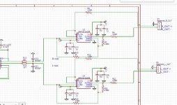
Components finally arrived, finished balanced out. Notice slightly different sound between single-ended & balanced. For one, balanced has lower volume gain( Okay for me as I have enough). Mod PCB circuit schematic is in the picture below.
Am using TPA3255EVM amplifier, which uses ne5532 to make differential/balanced signal when input is single-ended (According to the guide - attached in the picture below). It also use the same op-amp as buffer when input is balanced.
I'd like to ask if there's any mistakes or improvements can be made to improve the sound. Any comments will be appreciated as always.
Thanks & Cheers,
Kay.
Hi Mark/ Members,
Components finally arrived, finished balanced out. Notice slightly different sound between single-ended & balanced. For one, balanced has lower volume gain( Okay for me as I have enough). Mod PCB circuit schematic is in the picture below.
Am using TPA3255EVM amplifier, which uses ne5532 to make differential/balanced signal when input is single-ended (According to the guide - attached in the picture below). It also use the same op-amp as buffer when input is balanced.
I'd like to ask if there's any mistakes or improvements can be made to improve the sound. Any comments will be appreciated as always.
Thanks & Cheers,
Kay.
Attachments

Hi Kay,
Not sure how you came to be using 4.99k resistors in series with the balanced outputs? 220 ohms should be plenty, and some people use even less. That might account for the loss of volume you report.
Regarding a change in sound from using balanced interconnects, mostly that would be used to help with ground issues between the dac and the power amp. Things like hum, buzz, and or noise pickup (and or more subtle SQ problems) caused when the two devices are connected should be improved. Especially so, if that was one of your biggest remaining problems with sound quality. At this point, I'm kind of guessing it may not have been. Ground problems can cause significant sound quality issues, so comparing balanced with unbalanced in your situation was still a wise thing to do, IMHO.
To make much more in the way of gains in sound quality, you may have to find some way to so you can program the dac registers. Improvements do come with that. Since you have AK4137 and hopefully have hooked up I2S carefully, you should be able to reduce DPLL bandwidth a least a bit for an immediate improvement. If you have RPi, you could try that. If you had a PC, Mac or Linux sound card with line input, we could also talk about how to reduce harmonic distortion in the dac. Those kinds of things are necessary to get the best out of synchronous AK4137 clocking anyway, so hard to avoid them at some point.
EDIT: Another thing that might matter in your particular setup might be to try another power amp or headphone amp. Don't know if it is a limiting factor now, but if not now and if you keep making the dac better, it won't be too much longer before the amp probably becomes the main sound quality limiter.
Last edited:
Hi Mark,
I see. I did not know that 220 ohms is enough. No wonder, I thought the sound was a little choked. I can rectify that easy enough. Just to order the low value resistors & change them on the pcb.
Regarding dpll setting, I already put it to no. 1 setting on my rpi with i2c & i2s connection using the volumio plugin mentioned by eslei. I just don't know if it stays that way when I connect it back to xmos. I just could not get the sound to come out using the rpi, that I know is software related so I hope to manage it later.
I also have a windows/linux pc and asus xonar sound card which I believe has input. I'd like to try programming the registers to reduce harmonic distortion. Just do not know where to start.
Regarding my amp, I know it will soon be the bottleneck. But for now, I am amazed at how good the modded dac sounds in them.
Thanks,
Kay.
I'd like to try programming the registers to reduce harmonic distortion. Just do not know where to start.
Hi Kay,
You may need a notch filter, but I will explain the basic idea. The way it works it is use something like the free version of Arta software. If you put it in spectrum analyzer mode, you can display an FFT from the input of your sound card. The sample rate of the sound card set in Windows control panel should be the same sample rate Arta is set to (unless your sound card has ASIO drivers, in which case you have better options). The signal generator in Arta is configured to send out a 1kHz tone which is played back by the dac. The dac output goes back into the sound card input (or through a 1kHz notch filter first, then into the soundcard, which is the best way). You would then use some averaging of the FFT display to reduce any noise until you can see the harmonics of 1kHz. The 2nd harmonic is a 2kHz, and the 3rd is at 3kHz. There shouldn't be much if any higher harmonics, or there may be other problems in the dac. You adjust the harmonic compensation registers for H2 and H3 to minimize the 2nd and 3rd harmonics as seen on the FFT. Write down the numbers, as they don't stick in memory anywhere.
I will send a PM with one or two other bits of info, but the above is the basic idea. Basically, there are two sets of registers for distortion compensation adjustment and another register to enable the compensation to work. Its all in the datasheet.
I have an Arduino program I think it should be okay to link to, since it is a general purpose I2C program. It can read and write a selected 8-bit register in a registered I2C device, it can also read/write signed 16-bit ints, and read 32-bit ints. That's enough (barely). Link ...With it, a data sheet, and an understanding of the what the data sheet is telling you, it is possible to control just about any registered I2C device. It is not limited to any particular device. I will probably use it for initial testing of AK4499, and then change it around to make the settings I use the most often more convenient to access.
Also, I have have a schematic of a common type of notch filter if you want to build one. It takes two or three opamps and requires a little adjustment to set the null properly, but I can explain if anyone is interested.
Last edited:
Thanks Mark,
I think my card has ASIO. I will take time to follow the procedures.
Regarding the balanced resistors, what will be best to use? 220 ohm .1% 65mw will be okay? Some schematics also use small capacitors like 470pf on the circuits, are they needed?
Regards,
Kay
I think my card has ASIO. I will take time to follow the procedures.
Regarding the balanced resistors, what will be best to use? 220 ohm .1% 65mw will be okay? Some schematics also use small capacitors like 470pf on the circuits, are they needed?
Regards,
Kay
Good! It should continue to get better as you make more modding progress.
Using the wrong capacitors could make it oscillate, or using the wrong load. Presumably, any ceramic caps should be X7R, and any electrolytics should be standard (cheap) types, not low ESR. Those things are to control the phase shift that the error amplifier sees at its input (and throughout the error amp feedback loop). Regarding the audio opamp output stage circuit that the regulators are to be used with (aka, the 'load'). Only use .1uf X7R ceramic bypass caps at each of the opamp power pins, no other filter caps (remove any other power rail filter caps from the output stage circuit, if there are any). The only electrolytic caps should be the ones on the Nazar regulator board. Too much capacitance at the output (that is still effective at high frequencies) is what will make it oscillate. Maybe try just using a carbon or metal film resistor test load to start with, and see if the regulators are stable with that. If not, then there is something wrong with the regulator circuit layout and or with its components.
EDIT: Also, I don't recall if you are supply 5v for the 3.3v regulators from an external 5v supply, or if you are using the original 5v regulator that comes with the dac board. That might draw too much current for Nazar regulator., and it might have an input cap that is causing phase shift too.
When it comes time to try the regulators with the opamp output stage load, then the Nazar regulator should be located physically close to the opamps so that any wire resistance from the regulator to the opamps causes as little voltage drop as possible. Probably better not to use the regulators for an AVCC opamp supply until you know they are stable. Don't want to risk blowing up the dac chip by accident.
Regarding an input voltage reference for a an opamp AVCC supply, you could use a low noise LDO for that if you don't want to buy an LTC6655. A 3.3v ADM7154 that isn't being used for anything else could be used, for example.
So far I only use the X7R 10UF output capacitor on the output. And load resistors. In the LM trim, I use the Panasonic EEUFM1E101 LOW ESR. Nazar recommends putting them, for their "reasonable sufficiency".
I no longer use the 5V regulator on the board. I made it from a separate transformer winding. And from bipolar voltage, only one operational amplifier is powered at the output.
what voltage and current was set for the reg? the current through the shunting transistor cannot exceed yielding 0.35w max, if sot23 package used. if you need more current, use to126. can be easily soldered on sot23 pads. and add heatsinks as well.
Напряжение на входе 20 вольт, на выходе выставлено примерно 15в (подстроечный резистор выставлен на 3 ком) Ток посчитал с запасом, резистор получился - 10ом. На выходе на каждое плечо нагрузка в 1000ом. Одно плечо работает нормально и токозадающий резистор почти не нагревается. А вот во втором плече он сразу начинает дымится, моментально сгорает выходной транзистор.
The voltage at the input is 20 volts, the output is set to approximately 15V (the trimmer is set to 3 kom). The current counted with a margin, the resistor turned out to be 10ohms. At the output on each shoulder load in 1000ohms. +15 works normally and the current-generating resistor almost does not heat up. But in the -15 he immediately begins to smoke, the output transistor instantly burns.
I think my card has ASIO. I will take time to follow the procedures.
In that case, you should set the motherboard built-in sound device (or any other sound device you may have, just not your ASIO sound card) as the Windows default sound device. That way Windows will leave your ASIO sound card alone and you can set it directly using Arta.
Regarding the balanced resistors, what will be best to use? 220 ohm .1% 65mw will be okay? Some schematics also use small capacitors like 470pf on the circuits, are they needed?
Well, let's say your dac can put out 2v RMS of audio (maybe a bit less in reality). If the output resistors were shorted to ground at the amplifier end, how much power would they be dissipating? The formula is P = (E^2)/R. So, E is 2 which makes E squared = 4. Then, 4/220 = 0.018 = 18 milliwatts. That's plenty less than the rating of the 65mw resistors you have, so they should be fine.
Not sure where the 470pf caps you are talking about would be connected, but they are not typically needed, IIUC what you are talking about.
I no longer use the 5V regulator on the board. I made it from a separate transformer winding. And from bipolar voltage, only one operational amplifier is powered at the output.
IIRC, the original output stage has +-47uf filter caps at each end of the opamp for the +-15v rails? Also, there is typically an opamp input bias circuit in case the dac is to be operated from +15v only. That bias circuit may have an electrolytic cap on some styles of boards.
However, since you are using load resistors for now, any caps on the dac board can't be causing the negative regulator to burn. Perhaps you could attach a good in-focus, closeup picture of the layout? Maybe we will see something that stimulates some more thought about possible problems. Also, any chance of getting or using an oscilloscope? That should at least show if there is an oscillation or if there is some more or less DC runaway issue. If a high frequency oscillation, stray capacitive coupling due to layout could be a problem. If cap ESR is suspect, a small 1 or 2 ohm resistor could be put in series as a test. A current limiting resistors might be put in series with the LM337 input to keep anything from burning while you look at the circuit with a scope. In other words, various troubleshooting options might be possible depending on what resources can be made available.
Last edited:
Hi Mark,
On the ASIO on Arta, instructions noted.
On the caps, sorry am confused with the ess sabre reference evms circuit which do not use op amps. Thanks.
Kay
On the ASIO on Arta, instructions noted.
On the caps, sorry am confused with the ess sabre reference evms circuit which do not use op amps. Thanks.
Kay
IIRC, the original output stage has +-47uf filter caps at each end of the opamp for the +-15v rails? Also, there is typically an opamp input bias circuit in case the dac is to be operated from +15v only. That bias circuit may have an electrolytic cap on some styles of boards.
However, since you are using load resistors for now, any caps on the dac board can't be causing the negative regulator to burn. Perhaps you could attach a good in-focus, closeup picture of the layout? Maybe we will see something that stimulates some more thought about possible problems. Also, any chance of getting or using an oscilloscope? That should at least show if there is an oscillation or if there is some more or less DC runaway issue. If a high frequency oscillation, stray capacitive coupling due to layout could be a problem. If cap ESR is suspect, a small 1 or 2 ohm resistor could be put in series as a test. A current limiting resistors might be put in series with the LM337 input to keep anything from burning while you look at the circuit with a scope. In other words, various troubleshooting options might be possible depending on what resources can be made available.
Now I have transferred the converter board a little. I replaced the transistors in the SOT23 package with the TO92. I also moved the 10uf output capacitors as close to the transistor as possible. I noticed a non-soldered leg of a capacitor, just on the line that did not work (I bit off her too much).
And it seems everything worked! I set the voltage to 15.00V and it stably fight, even after warming up the transistors. The no-load current is 70ma (Not very economical). The output current is 15 mA respectively.
Now, probably, I'll try to install this board in my DAC.
Unfortunately, I do not have an oscilloscope. After all, with the help of it you can do so much! Soon I will buy myself an oscilloscope at 200mhz 1gsa / s. I think this will be enough for a newbie like me.
PS I still have 47uf capacitors on the DAC board for each + -15V line. I removed the extra capacitor that was on the +15 line -> +5, since it is no longer needed. Now the capacity at + - 15 is the same. I did not understand a bit about the bias scheme. This is Vref, as I understand it? I wanted to redraw the circuit with face values, in order to transfer it to 3 operational amplifiers in the future. But still did not.


An externally hosted image should be here but it was not working when we last tested it.

.
On the caps, sorry am confused with the ess sabre reference evms circuit which do not use op amps.
Those caps on the evaluation board differential outputs are for additional filtering since the differential signals were taken before the differential summing and filtering opamp stage. Since your balanced outputs are after the single ended output, no additional filtering should be needed.
Soon I will buy myself an oscilloscope at 200mhz 1gsa / s. I think this will be enough for a newbie like me.
Very nice! However, if you are not familiar with 200Mhz scopes, there will be some reading to do. Please let me know when the time comes and I will see what I have that may be useful.
I did not understand a bit about the bias scheme. This is Vref, as I understand it?
It is not Vref as we talk about with proper output stages. Rather, it is a network to suspend the original single opamp output stage half-way between the + and - power rails (rather than ground). If using +-15v power supplies, better to connect that node to ground. Its designed the way it is just in case someone decided to run the dac off of +12v or +15v only (with no negative rail). Bias network node is outlined in red box below.
Attachments

The voltage at the input is 20 volts, the output is set to approximately 15V (the trimmer is set to 3 kom). The current counted with a margin, the resistor turned out to be 10ohms. At the output on each shoulder load in 1000ohms. +15 works normally and the current-generating resistor almost does not heat up. But in the -15 he immediately begins to smoke, the output transistor instantly burns.
to me it appears that at 10ohms/15V you have about 45mA shunt current which is too high for sot23 transistors. if you want to stay with them, then go down to 12V and limit the current. at 15V I have 11R limiting R (2x 22R 1/4W in //) and BD139/140 for the shunt.
Just a little update on some recent activity here: I recently acquired one of the last few Neurochrome HD-1 headphone amplifiers (at closeout pricing 🙂 ). To make things interesting, someone brought over a Pass Labs HPA-1 headphone amp to compare with. HPA-1 has received a many good reviews, some awards, and has sold pretty well. It goes for something like $3.5k (even more than DAC-3!).
For the HPA listening occasion I moved modded dac#2 inside its big steel file server shielded case, DAC-3, and both headphone amps over to my workbench area. Also, moved a Monster HTPS 7000 MkII power conditioner so as to make possible comparisons with and without power conditioning.
First thing I did was plug every power supply for modded dac#2 into one un-conditioned power strip. There were three power supply transformers for the dac itself, one laptop PC SMPS power supply, one powered USB hub SMPS power supply, and two USB wall wart SMPS supplies used for Arduinos. As one could easily imagine, there were a lot switching power supply currents running around where they were probably doing more harm than good. I listened to modded dac#2 and was kind of disappointed in the SQ after all the work I put into it so far. Then I rearranged all the its power cords into different ports on the power conditioner. Ahhhh, much nicer sound. Very good in fact. Maybe the best I ever heard out of it. I then compared with DAC-3 using the Neurochrome HP-1 and some Senheisser HD 600 headphones. I was surprised that modded dac#2 sounded nearly the same as DAC-3, just a bit different in frequency response due to different digital filters.
About that time my friend with the Pass HPA-1 arrived and listened to both volume matched dacs using the Neurochome HPA, modded dac#2, and DAC-3. He asked me what he was listening to, and I told him which dacs they were, but not which switch position was which dac. He said this one sound fatter in the midrange in a nice way, and the other one sounds like it has more depth (less compressed dynamics). I told him the truth, the first dac was DAC-3 and other dac was modded dac#2. I could hardly believe he could be right that modded dac#2 could sound better than DAC-3 in some way, but I now have to agree he heard it correctly: It is possible to hear a bit more depth from modded dac#2 than from DAC-3 if using headphones. It was something I never noticed using speakers before. (Could be my speakers are compressed to some extent, if so maybe they tend to mask that difference in dacs. I will have to check into that possibility some more at another time.)
Later I tried the Pass HPA for the first time, and it initially it sounded very nice indeed, very musical, but then I realized it was a bit more distorted (mostly 2nd harmonic I found out later). When three vocalists sang at once in 'Black Cow' their voices were smeared together with no distinct reproduction of individual singer vocal sounds. With the Neurochrome, the voices were as distinct as I have ever heard them, and equally so for DAC-3 and modded dac#2.
Later my son came along, and I suggested he try out the Pass HPA while we have it here for a few days. He said at first it sounded really good, but it only took him a few seconds to realize it was more distorted. More instruments happened to come in at that time, and he said they were blurred together.
I have to say though, for being slightly distorted, it does have a very nice sound. The owner said he was aware of its sound, but said he judges audio equipment by how long one can continuously enjoy listening to it. He said for him to consider to piece of gear good, he has to enjoy listening to it for six hours straight. If he feels like he has had enough of listening to music before then, he classifies the piece of equipment as less desirable.
His comment was kind of interesting because I noticed before that I kind of enjoy listening to modded dac#2 longer than DAC-3, even though I know there is a slight FR technical flaw in the modded dac sound due to imperfectly balanced filtering in the midrange. I think what I like about modded dac#2 is the sound of synchronous DSD (even though it is only DSD256).
Okay. That's all for now. There is one other piece of gear here on loan for a few days and I will try to get to writing about it before too long.
Last edited:
Markw4, I arranged leasing AP 2702 for a week to remeasure my #9038S USB-dongle DAC+HPA project. SNR 122.2dbA instead of -125dbA according to my calculations. Also, I've prepared not so compact ES9038Q2M version of DAC+HPA with improved DAC power quality and XMOS USB bridge, that PCBA has SNR -123dbA. I didn't find the root cause of that 3db mismatch yet, probably AP has too sensitive front-end to USB HF common-mode noise, maybe my indirect measurement has a principal mistake. Similar situation with THD+N, at 0dbfs I see pretty good matching AP vs my ADC+notch reading but at -10db and lower AP shows the significantly worse value which strongly depends on A-weighting On/Off that's strange because my ADC(in 24/48 10-24000Hz mode) see there only 2;3;4;5 and 7 harmonics with no depends on A-weighting at all.
Attachments


Last edited:
Similar situation with THD+N, at 0dbfs I see pretty good matching AP vs my ADC+notch reading but at -10db and lower AP shows the significantly worse value which strongly depends on A-weighting On/Off that's strange because my ADC(in 24/48 10-24000Hz mode) see there only 2;3;4;5 and 7 harmonics with no depends on A-weighting at all.
Since you are measuring THD+N, how much of it is N when amplitude is at -10dB and lower? Is the A weighting responding to N? Only other thing that occurs to me is the ESS 'hump.' Don't know offhand why it would measure differently with different equipment.
Also, since this is a USB dac, any difference if run from a laptop PC operating on batteries, and with no connections to the power line or other equipment (the only connection being to the analyzer)?
- Home
- Source & Line
- Digital Line Level
- ES9038Q2M Board