Most thermal pads of the type you mention have HIGHER Thermal Resistance than thin mica with thermal paste on both sides.
That's correct, however there's several things to consider. For example you mention thin mica, the range of what's considered 'thin' varies substantially, as is the thickness of the (generous) application of thermal paste.
In my experience more consistent results can be obtained with thermal pads of the type I mentioned in my previous post than the application of thermal paste and mica, for the simple reason that most of the tolerances and faults in application are taken out of the equation.
Thermal coupling was good enough. And it does not explain DC output fluctuations.
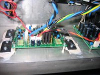
Well, judging by some of the experiences of people that have built the ExtremA it does. I've seen a few cases where people have mounted the two output stages of the ExtremA on thermally not connected heatsinks, one DIY-er had one heatsink fitted to each pair of output transistors using them as sidepanels for a slim mono-block case with the transformer in between. The temperature difference between the two heatsinks resulted in a DC offset at the output that varied with the temperature difference between them.
From that it can be reasonably expected that if one, or more, of the output transistors sees a higher thermal impedance than the others a similar effect could be observed.
I'm not saying that this is at the root cause of any DC fluctuations, it however is something that needs to be considered when building the amplifier.
Going forward, and considering you've evaluated Bohdan's build, have you measured these DC fluctuations, and if so, what magnitude are we talking about here? uV? mV? V?
Yes, but if you let it be so, it is wrong..Because with this DC gain (useless, it is audio amp) you will amplify each internal DC error voltage (input ofset voltage, raising 1/f input noise at sub Hz frequencies, DC thermal drift) , not only DC error from previous signal source ..So simplest way in this topology is to use two input caps, and take advantage of 100% DC NFB.It is basically a power differential opamp, so of course AC gain = DC gain, it would be silly if that wasn't the case.
I've seen a few cases where people have mounted the two output stages of the ExtremA on thermally not connected heatsinks,
Not the case here. Sander, please stop these steps aside
") . And output had fluctuated in hundreds of millivolts.
. And output had fluctuated in hundreds of millivolts.Attachments
And output had fluctuated in hundreds of millivolts.
Hundreds of millivolts? OMG! I have never seen, or heard, that complaint to be honest, so it would be interesting to see where this large DC offset comes from. I am failing miserably with trying to simulate such behavior in the simulator, even when running a .step function with temperature variations on the input transistors/cascodes and OPS.
So unless you have any suggestions I'm at a loss to provide an explanation for the DC offset you mention you measured on Bohdan's build.
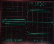
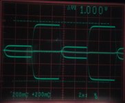
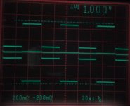
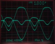
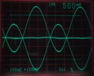
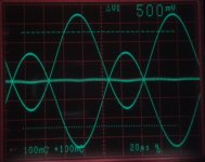
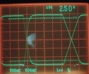
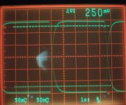
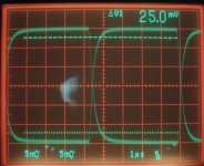
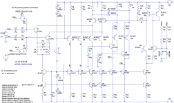
First results of the outputs of PRE and PRE + with modifications by BV.
Thanks
Cheers,
Bohdan
Thanks
Cheers,
Bohdan
Attachments
-
 ExtremA_frontend_square_10OkHz_5Vp-p.jpg257.1 KB · Views: 86
 -
 ExtremA_frontend_sq100kHz_5Vp-p.jpg268.3 KB · Views: 97
 -
 ExtremA_frontend_sq10kHz_5Vp-p.jpg255.9 KB · Views: 90
 -
 ExtremA_frontend_100kHz_limit.jpg289.3 KB · Views: 360
 -
 ExtremA_frontend_10kHz_limit.jpg276.3 KB · Views: 364
 -
 ExtremA_frontend_100kHz_5Vp-p.jpg283.8 KB · Views: 392
 -
 ExtremA_frontend_10kHz_5Vp-p.jpg279.5 KB · Views: 427
Front end with 12k+2k2 ohm resistive load. Voltage range is necessary to multiply x10 (probes are adjusted 10:1). Then you will get the output amplitudes 29Vp-p, 2,9Vp-p and 290mVp-p from PRE+ and PRE-
Attachments
Last edited:
These scope shots refer to last modification by BV...
These adjustments do not solve the instability and oscillation.
Proper SR is fixed with the changes I propose, I've got confirmation from two people already that implemented these changes, which matches the results in the simulator.
I'm not aware of any DC stability issues. It obviously has a DC offset trimmer fitted for a reason, set that with inputs shorted to GND after about 30 min warmup. However if you still see a shift in DC at the output then your source is likely the culprit here, make sure it is free of DC errors.
Clipping behavior is also fixed with the changes I propose as the loop is far more stable, hence clipping is also much better behaved.
I do however question what you are driving with this amplifier if you run it into clipping often, that means you're driving >100W into 8 Ohms. Take note that only 50W is available in 4R and even less at lower impedance due to the principle of operation of a class-A amplifier.
Hi Sander,
I've just bought 3 sets of PCBs from you, does version 2 BoM contains those cap changes? Anything else I should get before I close my Digikey order?
Thanks
Do
I was wondering which bridge rectifiers would be ideal
Was thinking of this type
http://www.digikey.ca/scripts/DkSearch/dksus.dll?Detail&itemSeq=162408154&uq=635534213113652654&CSRT=3438505757611266754
But I believe Fast with soft recovery would be much better, unfortunately it is not easy to get a PCB just for bridge... I don't want to use P2P since I want this to look really "elegant". Any idea?
Thanks
Do
@Bohdan,
I appreciate the effort, however in order to make sure the modifications you've made to the design are actually worthwhile it is absolutely essential to compare directly to the original design. Without that comparison the scope shots etc. you've posted only illustrate that the amplifier has not been modified to the extend it stops working.
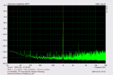
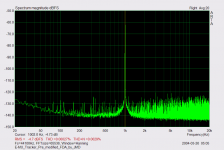
I would like to suggest you build up one channel in stock configuration and the other with the modifications proposed by BV. Then subsequently perform the same measurements on both, under the exact same conditions. From looking at your FFTs I however question your ability to make accurate THD measurements, your soundcard could be the limiting factor here? The THD@1K FFTs you posted are in the order of three (!) magnitudes worse than what has been measured on the original ExtremA using a AP audio analyzer, the THD@1K at 40W/8R was >-150dB, or 0.0000032%, a value that cannot be measured directly.
Only then we'll getting verifiable data that can be used to possibly further improve on the design. So please be very meticulous with what you're measuring and verify, compare and document each measurement, otherwise I'm afraid it is a bit of a wasted effort.
I appreciate the effort, however in order to make sure the modifications you've made to the design are actually worthwhile it is absolutely essential to compare directly to the original design. Without that comparison the scope shots etc. you've posted only illustrate that the amplifier has not been modified to the extend it stops working.
I would like to suggest you build up one channel in stock configuration and the other with the modifications proposed by BV. Then subsequently perform the same measurements on both, under the exact same conditions. From looking at your FFTs I however question your ability to make accurate THD measurements, your soundcard could be the limiting factor here? The THD@1K FFTs you posted are in the order of three (!) magnitudes worse than what has been measured on the original ExtremA using a AP audio analyzer, the THD@1K at 40W/8R was >-150dB, or 0.0000032%, a value that cannot be measured directly.
Only then we'll getting verifiable data that can be used to possibly further improve on the design. So please be very meticulous with what you're measuring and verify, compare and document each measurement, otherwise I'm afraid it is a bit of a wasted effort.
@Do,
Just ping me via email, changes are just two capacitor values that need changing. As for your bridge rectifier question, just pick any chassis mounted type that has ample current handling capacity, as it needs to be mounted to the chassis for cooling. For example:
GBPC3502-E4/51 Vishay Semiconductors | Mouser
@Bohdan,
I appreciate the effort, however in order to make sure the modifications you've made to the design are actually worthwhile it is absolutely essential to compare directly to the original design. Without that comparison the scope shots etc. you've posted only illustrate that the amplifier has not been modified to the extend it stops working.
I would go even farther, the screenshots and FFTs that Bohdan is showing now are misleading, regarding original design, and might be confusing.
The +SR and -SR slew rate non-symmetry shown is for the reason of DC trimpot setting close to one of its ends.
- Status
- This old topic is closed. If you want to reopen this topic, contact a moderator using the "Report Post" button.
- Home
- Amplifiers
- Solid State
- ExtremA, class-A strikes back?