How did you know? Have you measured that amplifier, Federmann?
Knowledge, experience and practice, taught me to deal with high frequency stability. The circuit is simulated wrong. The circuit is unstable at high amplitude. I wrote earlier that this is not a good solution.
Good luck
Bobby
Knowledge, experience and practice, taught me to deal with high frequency stability.
Wow!
Knowledge, experience and practice, taught me to deal with high frequency stability. The circuit is simulated wrong. The circuit is unstable at high amplitude. I wrote earlier that this is not a good solution.
Good luck
Bobby
Alright, I'll bite, what do you suggest? We'd all like to learn, especially from someone that appears to be really sure of himself.
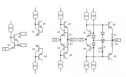
Here’s a thought experiment to illustrate my comment about Barry Blesser’s correspondence in the Journal of the IEEE (June 1970). Remember this is from the formative days when a way to connect two transistors might actually be novel. In the figure the first example is what was published, presented as a “super” transistor with much reduced Vbe error. This of course is due to Q1 acting as an amplifier in a feedback-loop enclosing the Vbe error of Q2.
Next let’s make a complimentary version and then adding two resistors it begins to look familiar. Q3 and Q4 can be Darlington’s or TEF’s without losing the point, I just left them out for visual simplicity. The last would be a logical class A/B version of this error correction technique. With Q2 and Q4 heavily biased I don’t see much difference in performance from the previous “real” class A version with the added benefit that the output resistance is nominally “0” while the former is R1 || R2 and the transition from class A to class B is very gradual or you could even argue non-existent.
So I guess the error corrected output stage was virtually there the proverbial 40 yr. ago.
Attachments
Alright, I'll bite, what do you suggest? We'd all like to learn, especially from someone that appears to be really sure of himself.
1) Connection is drawn very confusing
2) RC members C7-C8 II R3 (C11-C12 II R4) the total negative feedback decreases the cutoff frequency, this requires an individual adjustment.
3) RC members C7-C8 II R37-R39 (C11-C12 R44-R48 II) local positive feedback increases the gain at high frequencies, increases the instability of the circuit at high frequencies.
4) False Boucherot R31-C4 (R40-C9), many RC (CBE, CBC), many individual settings. Were it not good for repetitive manufacturing.
So I guess the error corrected output stage was virtually there the proverbial 40 yr. ago.

Here’s a thought experiment to illustrate my comment about Barry Blesser’s correspondence in the Journal of the IEEE (June 1970). Remember this is from the formative days when a way to connect two transistors might actually be novel. In the figure the first example is what was published, presented as a “super” transistor with much reduced Vbe error. This of course is due to Q1 acting as an amplifier in a feedback-loop enclosing the Vbe error of Q2.
Next let’s make a complimentary version and then adding two resistors it begins to look familiar. Q3 and Q4 can be Darlington’s or TEF’s without losing the point, I just left them out for visual simplicity. The last would be a logical class A/B version of this error correction technique. With Q2 and Q4 heavily biased I don’t see much difference in performance from the previous “real” class A version with the added benefit that the output resistance is nominally “0” while the former is R1 || R2 and the transition from class A to class B is very gradual or you could even argue non-existent.
So I guess the error corrected output stage was virtually there the proverbial 40 yr. ago.
yep.
-RNM


Great. I want to build one! Been looking for some cancellation/correction circuits instead of only nfb to reduce distortion. Nice single transistor combiner/canceler. Does it clip well behaved? Need circuit schematic with some values. Looks like a simple mod to some existing amps will work, also. Going to look at some of the amps lying around here to modify. What are the pitfalls to avoid here? Thermal Stability? [#444]
-THx-RNMarsh
-THx-RNMarsh
Last edited:
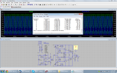
Just for fun - works perfect and sound is amazing!
PMA - headphone amplifier as remarkable.
I keep my thumb.
Last edited:
Just for fun - works perfect and sound is amazing!
No GNFB?
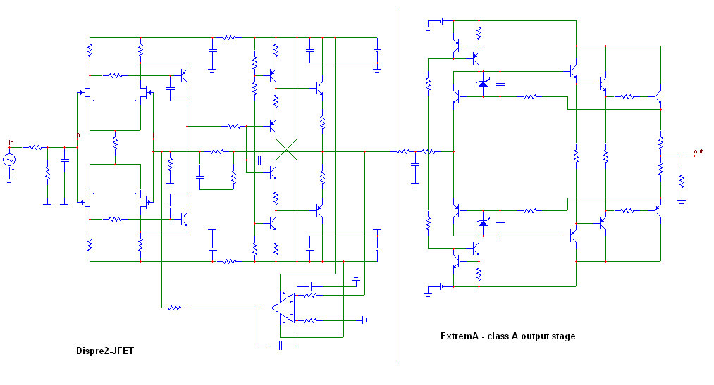
No GNFB, because this output stage operating in class A has distortion well below 0.001%, so there is no reason to put the buffer into GNFB.
It is a "small power" amplifier, like 12W/8 ohm or 20W/4 ohm. However, increasing rail voltages of the preamp would give more power.
It is a "small power" amplifier, like 12W/8 ohm or 20W/4 ohm. However, increasing rail voltages of the preamp would give more power.
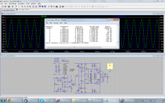
Or, as per Scott's suggestion, with a Class-AB output stage (output darlingtons + string of diodes = Sanken STD03N/P), in order to drive this beyond ~30W/8R a different input stage is needed that allows higher voltage swing. THD20K@30W/8R is listed, which is about 2x that of the class-A approach in my previous post.
Attachments
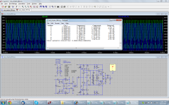
And after a bit of tweaking the standing currents and changing the bias voltage on the output transistors from ~2mA to ~60mA I arrive at the following. The delta between the THD20K result at the output of the amplifier and the input of the opamp who's NFB loop is tied around the OPS is a mere 0.000066%!
Attachments
No GNFB, because this output stage operating in class A has distortion well below 0.001%, so there is no reason to put the buffer into GNFB.
It is a "small power" amplifier, like 12W/8 ohm or 20W/4 ohm. However, increasing rail voltages of the preamp would give more power.
PMA, what is your bias current 5A?
To be throwing hot.
Last edited:
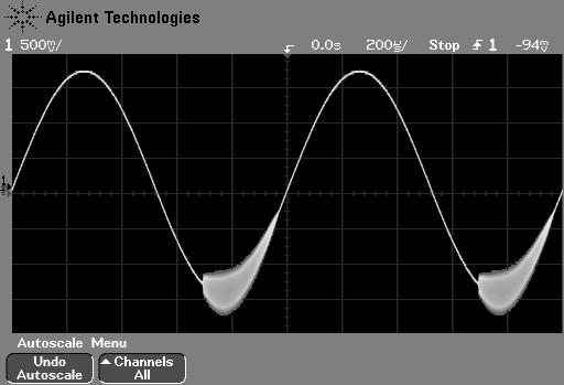
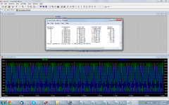
when shifting into Class B you get e tremendous increase in distortion.
With ~2mA and ~60mA of bias as posted above and the simulated figures for THD20K at 30W/8R it is pretty clear that we're well in class-B territory.
PMA, what is your bias current 5A?
To be throwing hot.
Around ~2A if I'm not mistaken?
- Status
- This old topic is closed. If you want to reopen this topic, contact a moderator using the "Report Post" button.
- Home
- Amplifiers
- Solid State
- ExtremA, class-A strikes back?