Yes, who would have a stereo microscope on his bench for SMD soldering .......
As already pointed out, he cross feed attenuate the signal by a factor of 3.
The gain is to compensate for that.
You can reduce the gain when not using cross feed.
Patrick
Overkill ? I actually paid that microscope less than a enlarging lens. It's a real game changer.
As the cross feed circuits are passive, I would like to play with them putting them between the source and the F5-H first before trying to integrate them in the box.
I have the 100k input resistors on the input connectors.
Should I remove these if I use the cross feed ?
Thanks,
Davide
> I actually paid that microscope less than a enlarging lens.
Can you get me one ?")
> As the cross feed circuits are passive, I would like to play with them putting them between the source and the F5-H.
Firstly you need to make sure the source can drive the cross feed (say ~ 10k).
Then you should add a buffer after the passive filter.
Else the bandwidth and frequency response of the F5-HA will suffer.
A source follower is just fine.
> I have the 100k input resistors on the input connectors.
> Should I remove these if I use the cross feed ?
Not if you have a buffer in between.
P.
Can you get me one ?
> As the cross feed circuits are passive, I would like to play with them putting them between the source and the F5-H.
Firstly you need to make sure the source can drive the cross feed (say ~ 10k).
Then you should add a buffer after the passive filter.
Else the bandwidth and frequency response of the F5-HA will suffer.
A source follower is just fine.
> I have the 100k input resistors on the input connectors.
> Should I remove these if I use the cross feed ?
Not if you have a buffer in between.
P.
So basically I can add a DCB1 (that I am familiar with) after the Cross Feed that was described in the F5H document. I can derive the +-15 by the same regulators that feed the F5H. (How do you handle the power in your design ?)
Correct ?
If I understood well, the input impedance of the follower is much higher of the one of the input stage of the F5 and the passive nature of the cross feed gives it not enough current drive to properly handle the F5 input.
D.
Correct ?
If I understood well, the input impedance of the follower is much higher of the one of the input stage of the F5 and the passive nature of the cross feed gives it not enough current drive to properly handle the F5 input.
D.
> I am also in the middle of a new portable design with Zero Global Feedback but using IC's.
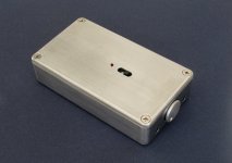
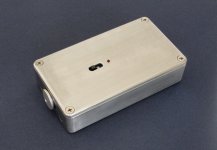
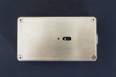
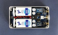
> It has a gain stage with ZGF followed by a follower driver stage, using 2x 9V batteries.
> It also has a cross feed buffer, all in a Hammond 1550B case.
http://www.diyaudio.com/forums/pass-labs/271926-f5-headamp-7.html#post4523035
Shown here without the crossfeed (to make testing easier).
Already listened for some 3 hours with alkaline batteries.
More to come in a separate thread once fully finished.
Patrick
.
Attachments
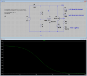
Why is it so difficult to download LTSpice (for free) ?
Patrick
.
Hi Patrick,
New to LTspice, just installed the version IV and try to load the
"Nazar 317_337 PSU Load Reg Amplitude.asc" but got message of missing symble for LM317 and LM337.
Thanks
We have none of the aluminium angles left (just bought enough for our own use), and we do not intend to do mechanical parts in the future.
But you can do something similar to this :
http://www.diyaudio.com/forums/pass-labs/283387-f5-ha-build-thread.html#post4624605
And note the commercial amp it now replaces.
The inside dimensions you can refer to the 2107 case you can find on ebay :
2107 Full Aluminum Power Amplifier Enclosure Headphone Amp Preamp Case DIY | eBay
Roughly 160 x 60 x 240mm.
Patrick
Noob First Build
Dear cloud85,
Thank you and EUVL !
This is my first project. Can you post a link to the mouser project file ? I am planning on the simplest build (2) F5-HA Amplifiers, lm317/337 regulator, 10k pot and 50va transformer, 15 volts.
Thank you you for your patience.
All the best.
The F5-HA mouser project file with recommended parts cost around SGD 150. This excludes the talema transformers, matched LDRs, LDR pot, matched FETs(2SJ74/SK170, Fairchild devices) chassis and PCBs.
Dear cloud85,
Thank you and EUVL !
This is my first project. Can you post a link to the mouser project file ? I am planning on the simplest build (2) F5-HA Amplifiers, lm317/337 regulator, 10k pot and 50va transformer, 15 volts.
Thank you you for your patience.
All the best.
Not recommended for first project.
The Pass DIY headamp would be a much better choice.
http://www.diyaudio.com/forums/pass-labs/271662-new-passdiy-headphone-amp-coming-soon.html
Patrick
The Pass DIY headamp would be a much better choice.
http://www.diyaudio.com/forums/pass-labs/271662-new-passdiy-headphone-amp-coming-soon.html
Patrick
Thank you Patrick
Dear Patrick,
Thank you for the suggestion. It is midnight here, starting to go through the Pass DIY headphone amp pages.
All the best,
- Mark
Not recommended for first project.
The Pass DIY headamp would be a much better choice.
http://www.diyaudio.com/forums/pass-labs/271662-new-passdiy-headphone-amp-coming-soon.html
Patrick
Dear Patrick,
Thank you for the suggestion. It is midnight here, starting to go through the Pass DIY headphone amp pages.
All the best,
- Mark
Hi Patrick,
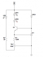
In the official build guide (http://xen-audio.com/documents/f5ha/F5-HA%20Description%20V1.4.pdf), the BOM of the LDR CCS is given on page 19. However, I cannot find the CCS schematic in the build guide.
Is the attached a correct guess of the LDR CCS circuit (using the components from the BOM)?
Thanks and regards.
Attachments
Last edited:
Attachments
Last edited:
- Home
- Amplifiers
- Pass Labs
- F5 Headamp ?