My 13x13 Maltese nested horns were a lot of fun, but most have been reused as patio furniture..*drools*
Attachments


Last edited:
How can I simulate a multicell horn in hornresp? Would it just be the total S areas of all of the cells combined? Seems to make sense to me
Then one would divide the S areas into however many cells would be a part of the cluster?
Then one would divide the S areas into however many cells would be a part of the cluster?
The reason I ask is that I was getting something I was very happy with in FLH config with the 8FEs. Granted it was vented as well. But I am curious about this
3d Printable 50deg x 50deg 2-way synergy
JG,
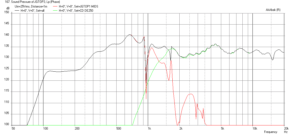
I think you might be happy with this design. I constrained myself to a 23 in x 23 in horn with a 50 deg H x 50 deg H cone angle. The length is 18 in not including the CD and a 3/4in thick mounting flange. It should be completely 3d printable assuming 0.5in thick walls on the horn. You could print braces and support struts to your heart's content to make it stiffer but I figured a 0.5in thick ABS wall is plenty thick. I am surprised myself at how this turned out. It is using qnty 2 x 8FE200's (I am assuming you have 4 ohm units wired in parallel for your 2ohm amps). I am using the model of a B&C DE250 CD but you can substitute whatever you like as I am crossing over at a relatively high 1500Hz. The 8FE200's are mounted as close to the throat as possible and have the equivalent of a 2.75in dia CSA hole leading to the horn wall at a location 3in downstream from the throat position. The drivers will have a 3d form inside the cone to take up the conical volume of the cone and dustcap to reduce it to no more than 250 cc's. You need to leave some room for the cone displacement (191 cm2 x 0.5cm stroke is about 100 cc minimum, but make it 250cc to prevent cone slap at 12mm). This is important, as it allows the bandpass of the 8FE200's to go up much higher allowing the XO at 1500Hz (which is cleaner). The rear chamber on each 8FE200 is 15 liters, or you could combine both in one box for 30 liters. There are two 4.0 in dia (ID) ducts that are 7.0 in long from the chamber and fed to injection points located 13.0 inches downstream from the throat. The horn shape is 50 deg x 50 deg with a secondary expansion of 100 deg per the Bwaslo spreadsheet.
Here is the resulting max SPL output with a -24dB/oct BW at 98Hz HPF and a 24dB/oct XO at 1500 Hz. It only takes 25volts to reach xmax and you get 124dB SPL at 1m down to 100Hz. The horn is assumed to be in open field at a height of 60in above the ground. You can just EQ the midbass down and the CD down to match the BR output.
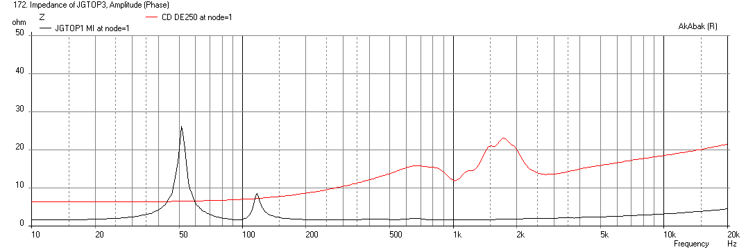
Here is the Impedance:
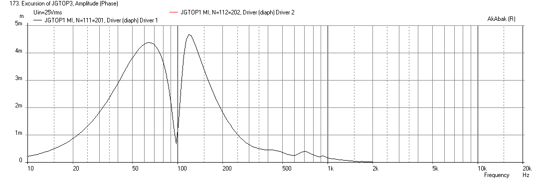
Here is the cone displacement at xmax (with filters):
Here is the electrical power input:

Once you CAD this up complete with driver mounts, cone volume filler, ports, etc. and make an STL file, get a big roll of ABS plastic for the printer, and press "PRINT". 😀
If we go further with this concept, probably deserves its own thread...
Attached is the Bwaslo spreadsheet with the settings and dimensions I used for the Akabak sim.
JG,
I think you might be happy with this design. I constrained myself to a 23 in x 23 in horn with a 50 deg H x 50 deg H cone angle. The length is 18 in not including the CD and a 3/4in thick mounting flange. It should be completely 3d printable assuming 0.5in thick walls on the horn. You could print braces and support struts to your heart's content to make it stiffer but I figured a 0.5in thick ABS wall is plenty thick. I am surprised myself at how this turned out. It is using qnty 2 x 8FE200's (I am assuming you have 4 ohm units wired in parallel for your 2ohm amps). I am using the model of a B&C DE250 CD but you can substitute whatever you like as I am crossing over at a relatively high 1500Hz. The 8FE200's are mounted as close to the throat as possible and have the equivalent of a 2.75in dia CSA hole leading to the horn wall at a location 3in downstream from the throat position. The drivers will have a 3d form inside the cone to take up the conical volume of the cone and dustcap to reduce it to no more than 250 cc's. You need to leave some room for the cone displacement (191 cm2 x 0.5cm stroke is about 100 cc minimum, but make it 250cc to prevent cone slap at 12mm). This is important, as it allows the bandpass of the 8FE200's to go up much higher allowing the XO at 1500Hz (which is cleaner). The rear chamber on each 8FE200 is 15 liters, or you could combine both in one box for 30 liters. There are two 4.0 in dia (ID) ducts that are 7.0 in long from the chamber and fed to injection points located 13.0 inches downstream from the throat. The horn shape is 50 deg x 50 deg with a secondary expansion of 100 deg per the Bwaslo spreadsheet.
Here is the resulting max SPL output with a -24dB/oct BW at 98Hz HPF and a 24dB/oct XO at 1500 Hz. It only takes 25volts to reach xmax and you get 124dB SPL at 1m down to 100Hz. The horn is assumed to be in open field at a height of 60in above the ground. You can just EQ the midbass down and the CD down to match the BR output.
Here is the Impedance:
Here is the cone displacement at xmax (with filters):
Here is the electrical power input:
Once you CAD this up complete with driver mounts, cone volume filler, ports, etc. and make an STL file, get a big roll of ABS plastic for the printer, and press "PRINT". 😀
If we go further with this concept, probably deserves its own thread...
Attached is the Bwaslo spreadsheet with the settings and dimensions I used for the Akabak sim.
Attachments
-
 3d-printable-50x50deg-jgtop-with-br-freq-1m.png42.7 KB · Views: 685
 -
Synergy Calc v5-JG-50-50-deg-3dprint.zip499.3 KB · Views: 105
-
 3d-printable-50x50deg-jgtop-with-br-Electrical-Power.png27.2 KB · Views: 613
 -
 3d-printable-50x50deg-jgtop-with-br-Displ.png29.6 KB · Views: 653
 -
 3d-printable-50x50deg-jgtop-with-br-Impedance.png28.3 KB · Views: 658
Last edited:
Simulate a single, then use the "multiple enclosure" (or whatever it's called) option. The simulation won't show the high frequency "fingering" inherent in HF multicells.How can I simulate a multicell horn in hornresp?
As a practical limit with Synergy type horns, for 90 degree coverage, one will be smoother than two, two will be smoother than four, etc.
That is the reason the 13x13 Maltese are patio furniture, and you will seldom see a DSL SH25 being sold since the introduction of the multi-HF driver 90 degree J series Synergys.
Art
How can I simulate a multicell horn in hornresp? Would it just be the total S areas of all of the cells combined? Seems to make sense to me
Then one would divide the S areas into however many cells would be a part of the cluster?
I don't think you can simulate groups of multicell horns in HR. Once you put a cellular wall, it is a separate horn. This can be simulated in Akabak, although I have never tried. It would just be a series of horns and they can either be connected to one driver chamber or each have their own. The horns would then have their output radiators specified so that the geometry matches a cellular horn with x-y offsets. You can even splay the angle for the rounded output mouth ones - a geometry spreadsheet needs to be developed to get cartesian coordinates for each cell's mouth xyz and 2-angles.
The system of individual horns would then have their wavefronts combine. If they were fed by a common chamber, the node limitation is 52 nodes about a 24 cells (2 nodes ea x 24 = 48 nodes) once you account for the 4 nodes a driver and compression chamber take up.
Xrk971,I am surprised myself at how this turned out. It is using qnty 2 x 8FE200's (I am assuming you have 4 ohm units wired in parallel for your 2ohm amps). I am using the model of a B&C DE250 CD but you can substitute whatever you like as I am crossing over at a relatively high 1500Hz.
The drivers will have a 3d form inside the cone to take up the conical volume to reduce it to no more than 250 cc's. This is important, as it allows the bandpass of the 8FE200's to go up much higher allowing the XO at 1500Hz (which is cleaner).
Nice work, (did about what I expected in level) though the compression ratio required to achieve that high of a crossover seems rather "ambitious" to me, and at high levels, the 8FE200 may not be as "clean" as a HF compression driver.
Seeing as Jennygirl already has 3" diaphragm drivers which have way more Sd than the B&C DE250, I'd suggest a lesser compression ratio and a lower crossover point, avoiding the nasty 8" glitches in the 800-2000 Hz region.
The larger front chamber, lesser compression ratio also is much easier to build.
Hey, could I interest you in doing a sim on the sketch I did in post #380, using BR tunings at around 60-80 Hz? Those 2.6 pound B&C 10CL51 10" are really a bargain (three for less than $300, 60Fs, 6mmXmax, 12 BL), and I have one 3" diaphragm Celestion CDX14-3050 burning a hole in my shop...
Art
Last edited:
Art- Funny that you mention the 10CL51, I have some I could pull from another project not currently being used much. I love that driver sooo much, they are in my favorite mobile rig in a BR enclosure. I love em!
Am I stupid or something for still considering the FLH style horn + center mount CD, for some reason I am still toootally drawn to it... probably because of the dimensions and I seem to be getting decent SPL in simulation.
I know others have said that beaming could result, but by how much? For other designs the dispersion is also an issue.
Simulation with parallel 2x 10CL51 (300W @ 4ohm)


If you could, I would really know what to love what is wrong with this? Part of me wants to go out and build this today just to see
I know others have said that beaming could result, but by how much? For other designs the dispersion is also an issue.
Simulation with parallel 2x 10CL51 (300W @ 4ohm)
If you could, I would really know what to love what is wrong with this? Part of me wants to go out and build this today just to see
Xrk971,
Nice work, (did about what I expected in level) though the compression ratio required to achieve that high of a crossover seems rather "ambitious" to me, and at high levels, the 8FE200 may not be as "clean" as a HF compression driver.
Seeing as Jennygirl already has 3" diaphragm drivers which have way more Sd than the B&C DE250, I'd suggest a lesser compression ratio and a lower crossover point, avoiding the nasty 8" glitches in the 800-2000 Hz region.
The larger front chamber, lesser compression ratio also is much easier to build.
Hey, could I interest you in doing a sim on the sketch I did in post #380, using BR tunings at around 60-80 Hz? Those 2.6 pound B&C 10CL51 10" are really a bargain (three for less than $300, 60Fs, 6mmXmax, 12 BL), and I have one 3" diaphragm Celestion CDX14-3050 burning a hole in my shop...
Art
I thought about XO lower too - if JG has a bigger CD already capable of crossing down around 700Hz it can be very workable. The lower compression ratio is easy to do and I fixtured since JG is going to bus it in 3d adding the compression plug in the chamber is no big deal. But that driver may not have the motor or cone strength to handle that kind of compression.
Sure, I can see if I can sim your design. Your sketch is a little rough on the eyes though. Do you have a better sketch with clear dimensions?
Not sure what you mean by FLH style horn + center mount CD. If you mean a HF horn within the mid horn, there are lots of problems with that compared to a Synergy. If you mean a HF horn between two mid horns, the problems are way worse.Am I stupid or something for still considering the FLH style horn + center mount CD, for some reason I am still toootally drawn to it... probably because of the dimensions and I seem to be getting decent SPL in simulation.
I know others have said that beaming could result, but by how much? For other designs the dispersion is also an issue.
If you could, I would really know what to love what is wrong with this? Part of me wants to go out and build this today just to see
The FLH design you simmed is not appear to be a "beamer", it's response is -10 dB (half as loud) at 1000 Hz, less than a BR would be. Considering the impedance is only around 2.6 (not 4) ohms in that region, you would need about 4000 watts to get the 1kHz level to equal the LF portion of the response.
Other than that...
Art
If you could, I would really know what to love what is wrong with this? Part of me wants to go out and build this today just to see
JG,
Nothing wrong with trying a build. That is why I make things out if foam core. To try it out with minimal time and material investment - also because I don't have a shop with power tools. Your HR sim looks like it should work although I am no HR expert - there are settings in there that I don't know what they do. With AkAbak you specify everything yourself so you know what is in he model. The rear chamber is important and I don't know how that is manipulated. This looks like something you could whip out in one long night. Go for it! It is a learning experience either way. You could always stick a bullet horn tweeter in the middle for a top. A CD horn might block the 500k to 1k region too much.
But then you now have a printable synergy design. With a little 3d modeling (which we know you are good at) you can have a truly unique and excellent sounding point source speaker. Synergies are kind of like TH's - listen to one properly set up and you may have a hard time going back.
Last edited:
Not sure what you mean by FLH style horn + center mount CD. If you mean a HF horn within the mid horn, there are lots of problems with that compared to a Synergy. If you mean a HF horn between two mid horns, the problems are way worse.
The FLH design you simmed is not appear to be a "beamer", it's response is -10 dB (half as loud) at 1000 Hz, less than a BR would be. Considering the impedance is only around 2.6 (not 4) ohms in that region, you would need about 4000 watts to get the 1kHz level to equal the LF portion of the response.
Other than that...
Art
Okay, neat. Thanks Art! I meant an HF horn within the mid horn. Sorry for the confusion, still learning the best terminology to describe what I mean.
If I cross from mid to high at 1000hz or slightly under, then my HF horn should be able to pick it up where the mid leaves off.. at least I would think so. This would leave the mid horn covering merely the 100-700hz range.
What is the extent of disadvantage with the HF horn mounted inside the mid horn? Obviously the issue is that the volume the HF horn and CD takes up interrupts the mid horn path.. But I'm wondering too how much of an extent, with the size of the mouth being so large. It makes sense to me that at lower frequencies (a la tapped horn) it is not so much of an issue, and that it probably becomes exponentially greater with rising frequency?
Thanks so much, glad to know I am on the right track with the FLH sim at least 🙂
JG,
A CD horn might block the 500k to 1k region too much.
Thanks, that kind of answers my question to Art!
But then you now have a printable synergy design. With a little 3d modeling (which we know you are good at) you can have a truly unique and excellent sounding point source speaker. Synergies are kind of like TH's - listen to one properly set up and you may have a hard time going back.
The problem is that I don't like the dimensions of the synergy, the 24" x 24" is blocky on top of the sub. I want this to look kind of like a cube when combined sitting on the sub. I know, probably silly reasoning, I am a stickler for aesthetics!
The synergy could be made flatter with a 17in high x 24in wide design for 50 deg H x 30 deg V. Does that look better?
Hi,
I just made a quick attempt at bwaslo's spreadsheet, and came up w/ the attached entry block for a 90H x 40V synergy horn that looks doable. This should give plenty of volume to design a BP6 for the 8 inchers. The heigh J of 16.998" plus maybe 2 layers of outside box (2*0.719") might be low enough? I added some notes on the right to explain the input choices.
Regards,
Attachments


Hi,
I just made a quick attempt at bwaslo's spreadsheet, and came up w/ the attached entry block for a 90H x 40V synergy horn that looks doable. This should give plenty of volume to design a BP6 for the 8 inchers. The heigh J of 16.998" plus maybe 2 layers of outside box (2*0.719") might be low enough? I added some notes on the right to explain the input choices.
Regards,
Tb46,
I essentially arrived at the same dimensions you did based on width and height constraints. The sim for this is in post 369. Basically set angles and adjust freq until width matches. This is not a bad design. Like I said, it can be 107dB sensitive by cutting the mids and horn.
Hi again,
Going through some old data files I found these entry examples: 8FE200 BP6 in CH and Nd:
(entry examples only, not worked out at all)
Regards,
What is CH and Nd? One thing I wish HR would do is spell out all the acronyms in the input window. There certainly is room.
Hi X,
Driver Arrangement, below Re.
CH = compound horn (S5-S6, L56 then becomes the reflex (back) port)
Nd = normal horn design
Usually, you would use CH for something like the Altec Voice of the Theatre. Or, just another way to do a BP6. But, it places the driver entry @ the throat of the horn.
Regards,
Driver Arrangement, below Re.
CH = compound horn (S5-S6, L56 then becomes the reflex (back) port)
Nd = normal horn design
Usually, you would use CH for something like the Altec Voice of the Theatre. Or, just another way to do a BP6. But, it places the driver entry @ the throat of the horn.
Regards,
What is CH and Nd? One thing I wish HR would do is spell out all the acronyms in the input window. There certainly is room.
On the input screen hover the mouse over the input and Hornresp will define it in the bottom line. That applies to every single input box and label on the input screen. CH is compound horn and Nd just stands for number of drivers, a holdover from when that was the only option. Nd is end loaded with S1 being the driver entry into the enclosure, whereas Od is offset driver with S2 being the driver entry.
If the simple description you get from hovering doesn't help click "Calculate" and see what the schematic looks like. If necessary make a change and go back to see what changed in the schematic.
This info is all in the Help file too.
And if you have any specific questions you can PM me. I'll help you learn Hornresp and you'll be surprised how easy it is. Sooner or later I was going to contact you anyway with a couple of questions about your Akabak sims.
EDIT - tb46 posted while I was typing, and while you could call Nd a "normal" horn, the distinction that the driver taps into the enclosure at S1 is important, and is what differentiates it from an offset driver horn where the driver taps in at S2.
Last edited:
- Home
- Loudspeakers
- Subwoofers
- FaitalPRO 15HP1060 vs 3015LF for tapped horn?