Another step closer, can hardly wait!
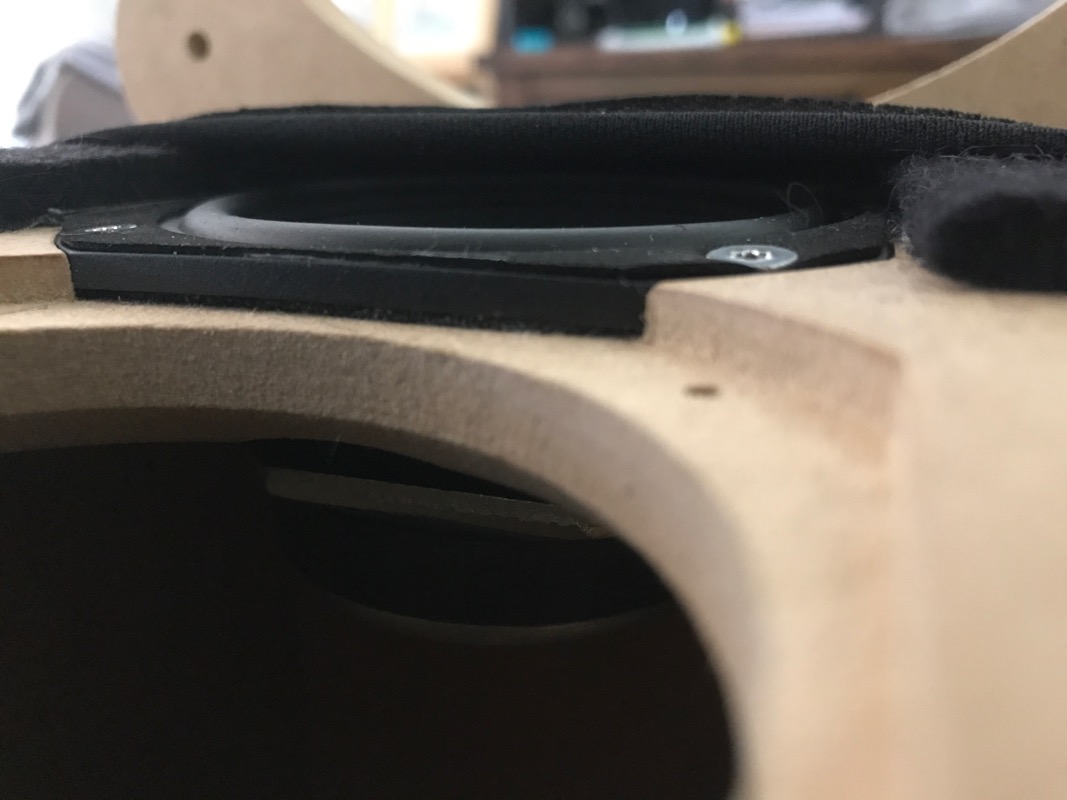
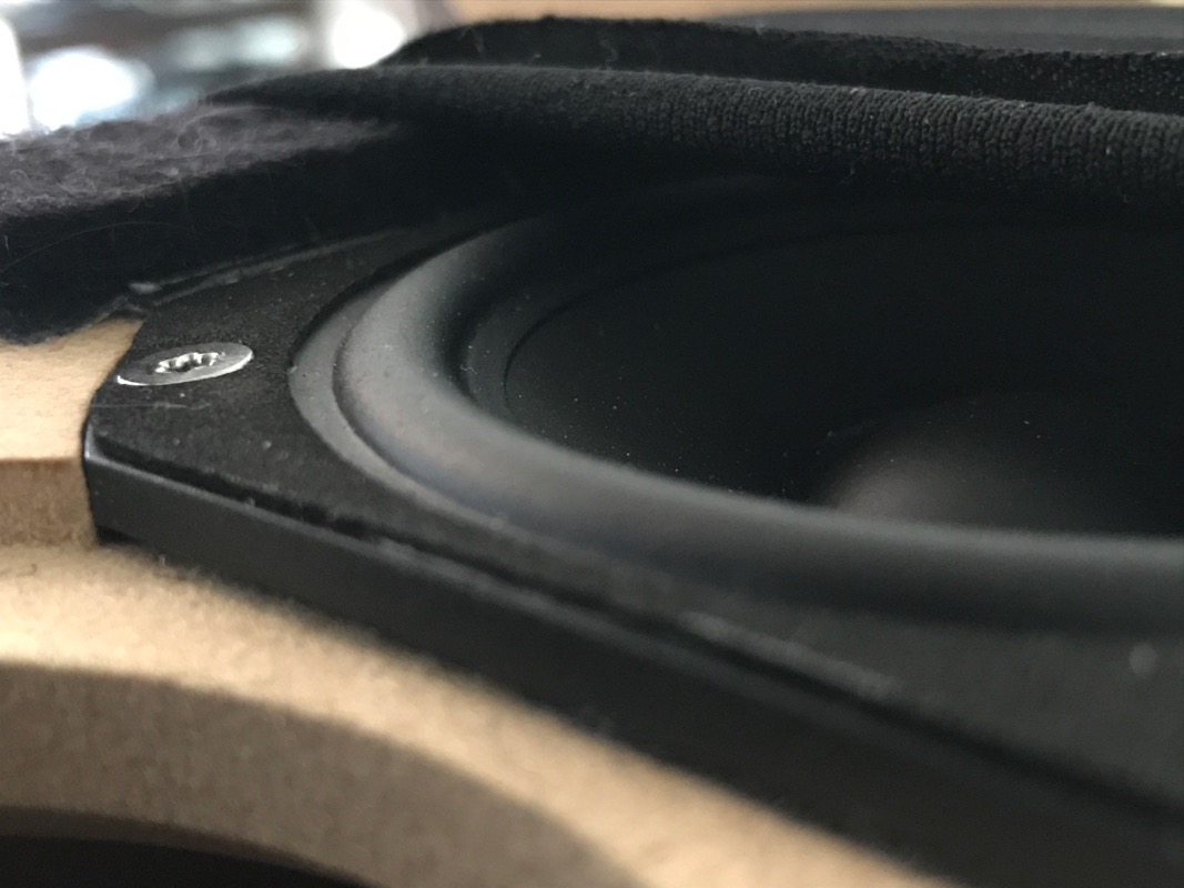
Still it's tough to see on these pictures how much room the surround has to move freely under the sock.
Still it's tough to see on these pictures how much room the surround has to move freely under the sock.
The moment of truth is fast approaching!Another step closer, can hardly wait!
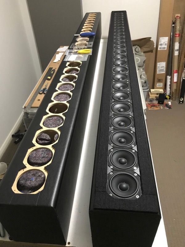
Yes it is very difficult to take pictures that show the full array and still have any detail!Still it's tough to see on these pictures how much room the surround has to move freely under the sock.
The surround is 1.75mm above the driver bezel and the felt is 4.8mm, so there should be 3.05mm gap between the surround peak and the fabric enough for xmax and a bit spare. I should also have a tiny bit extra as the gasket on the outside of the bezel will be flush with the vinyl so you can add the thickness of that gasket to the gap too.
I can always add some more if I see the sock blowing in the breeze 😀 But I don't think it will be necessary.
These pictures from earlier on when I mocked up the finish show it better.
You should be okay for clearance. My TC9 birdhouses have a good couple mm of cone movement, but even with the 6dB bass boost, they get plenty loud enough for normal listening. However when I crank the amp a bit more, it becomes apparent, muddying the midtones and treble a bit. Xmax does not mean absolute excursion limit, just that the voice coil is moving out of the sweet zone, damping mid and treble response at the extremes.
You have 50 drivers all firing at once, so shouldn't be an issue at sane SPL levels, taking into account the 3dB line array rolloff as opposed to 6dB point source. You are, however, applying a 15dB bass boost in the 20-40Hz region, so I imagine that will yield a bit of movement.
Good luck and keep us posted. Initial sound test won't be long off... 🙂
I'm fairly sure I will, I made some calculations to have enough space for the xmax of 2.6mm even though I doubt I will want or have the amp power to push it that far. 1/4" felt was much more expensive and I calculated that I didn't really need the extra space. But sometimes reality works out to be different than all the best laid calculations so we will have to wait and see 😉You should be okay for clearance.
I am aware that Xmax and Xmech are different 😉 Xmax can be a tricky parameter as there is no universal measurement standard that every manufacturer sticks to. The TC9 spec sheet also does not state how the figure was achieved. Generally it is where the coil starts to leave the gap and the distortion generated by excursion is no longer 'linear' but some manufacturers are much more conservative about where they say this happens. So the figure is either worked out from various dimensions or sometimes where harmonic distortion is at 10%. I would imagine the 'sweet zone' to be much lower than the Xmax figure.Xmax does not mean absolute excursion limit, just that the voice coil is moving out of the sweet zone, damping mid and treble response at the extremes.
Thanks, will do 🙂Good luck and keep us posted. Initial sound test won't be long off... 🙂

Thanks, I think Pano might have done more than just run an impedance test.Great to hear first 25 devices checked fine without the needle failure as Pano had in past : )
The second set tested out well too! With any luck I should be able to run some impedance tests on the fully wired cabinets tomorrow 🙂
Attachments

Your most extreme outliers for DC resistance appear to be 7.18 and 6.93. They are all well within 5% tolerance of each other which is good.
Yes I am pretty happy with the result, in general the closer the serial numbers are together the closer the results. It would also be easy enough to match the drivers if you only needed a few.Your most extreme outliers for DC resistance appear to be 7.18 and 6.93. They are all well within 5% tolerance of each other which is good.
Not a bad result at any price as a few percent tolerance usually costs much more 😉Not a bad result at that price, right? 😉
I didn't get as far as I wanted today but I have the divers installed and wired in one.
This one's for wesayso, I put a steel straightedge across the felt and measured the gap between the top of the surround and the top of the felt, it is actually just over 5mm which is more than enough room.
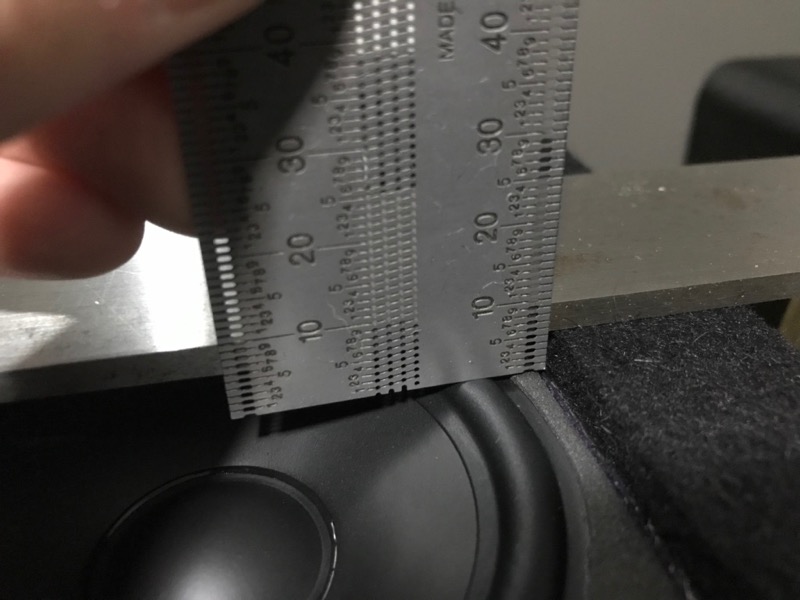
This one's for wesayso, I put a steel straightedge across the felt and measured the gap between the top of the surround and the top of the felt, it is actually just over 5mm which is more than enough room.
Attachments


No, my plan is to finish the other one without the felt for now and take some outdoor measurements to see the effect of the felt. Either way the felt will be used with the sock as it is needed to give room for the driver's excursion.Good progress. Did I miss before and after felt placement tests?
The double sided tape used to hold the felt on is very adhesive and does not come off well so testing with felt first and then without is not a good choice.
Interesting to follow also the upcoming research of front baffle felt test, based on BBC / T. Graversen / xrk971 / SpeakerDave tests seen from past expect it show bit better for HF part with felt there, but lets see how it works on longer designs : )
I have no doubt that felt can be useful in diffraction control, it will be interesting to see if the amount I have used here has any measurable effect. I won't be doing any audibility tests though and nor do I really want to wade into the mess of what can be measured vs what is heard 😉Interesting to follow also the upcoming research of front baffle felt test, based on BBC / T. Graversen / xrk971 / SpeakerDave tests seen from past expect it show bit better for HF part with felt there, but lets see how it works on longer designs : )
I needed to move the finished tower off the table and then realised that I didn't have any handy lifting points anymore now the drivers are in! Much more difficult and quite a bit heavier with the drivers in.
I have put some rubber feet on the bottom for now while I am testing as the spikes proved to be too sharp to be messed with.
I ran an impedance sweep on the finished speaker. The good news is that I wired it all correctly and it works. It is pretty smooth without any significant resonances. The bad news is that the split in the impedance peak is more pronounced than I was hoping for. I'm not sure if it will present any real problem. The only thing I can think of for the next one is to try and sort the drivers per sub enclosure to try and spread the variance, I'm not sure if this will make any difference but it isn't that much effort as I already have the individual impedance results including the serial number of the driver it related to.
I played some noise and sine waves through the impedance jig and you can hear the combing at very close distances if you move your head up and down but by the time you move back by a metre it has virtually vanished.
I also played a little bit of AC/DC through the headphone amp impedance jig (far from ideal!) and while it was quiet and had no bass it was not horrendous and sounded a bit like my portable radio 😀
Attachments


I wouldn't worry much about the tiny notch on that impedance curve. Seems like something fairly minor to obsess over. ACDC sounding like a portable radio through the headphone amp? Isn't that what the typical fullrange sounds like. You should build a one-high to test and see how it compares to the stack.
I once drove a pair of JP-500 (two way rugged studio monitor) from the headphone jack of my Cowon A3 media player once during a power blackout and they sounded fairly nice and distortion free with the volume set to 40 (max). So the argument that powerful speakers can't be driven at low spl levels is a misnomer.
Glad it's working out. Pumping 250 watts (5w rated * 25 drivers * 2 arrays) into the arrays would produce an insane amount of SPL so I doubt the drivers will ever get pushed to their capability. That extra headroom is good especially if you're gonna be boosting output into the bass region.
I don't think obsess is the right word, but I do believe it is important to try and get as many details right if you can. All the impedance measurements from similar line arrays have similar bumps so it is quite likely that it is just down to the fact that 25 separate drivers do not add together any better.I wouldn't worry much about the tiny notch on that impedance curve. Seems like something fairly minor to obsess over.
I have one simple thing left to try to see if it makes the result better so why shouldn't I try?
This is a comparison between the 5 drivers in free air, the best 5 driver result in a cabinet and the final 25 drivers. On that scale it doesn't look so bad. The more drivers you add together the lumpier the response gets at resonance. If I combined all the separate impedance measurement in REW it would probably look very similar.
And if I smooth the graph to 1/6 Octave, all the bumps are gone 😉
Yes that was the point even with no EQ it sounded like a small fullrange driver. Using a headphone amp through a 100 Ohm series resistor is not the normal way to power any speaker.ACDC sounding like a portable radio through the headphone amp? Isn't that what the typical fullrange sounds like. You should build a one-high to test and see how it compares to the stack.
Who made that argument?I once drove a pair of JP-500 (two way rugged studio monitor) from the headphone jack of my Cowon A3 media player once during a power blackout and they sounded fairly nice and distortion free with the volume set to 40 (max). So the argument that powerful speakers can't be driven at low spl levels is a misnomer.
Thanks, the First One amp I have ready to use with these is rated to 160W at 8 Ohms and I think that will be enough. I have a UcD 400 that can be tested which can produce 250W at 8 Ohms before distortion goes through the roof. The EQ eats power so final room position and bass boost needed will determine that.Glad it's working out. Pumping 250 watts (5w rated * 25 drivers * 2 arrays) into the arrays would produce an insane amount of SPL so I doubt the drivers will ever get pushed to their capability. That extra headroom is good especially if you're gonna be boosting output into the bass region.
Attachments


Sorry I didn't realise you were using a 100 ohm series resistor. That will definitely cause peaking at fs on the impedance curve. A few headphone amps are capable of driving 8 ohm loads; though many are not and some will distort or the internal impedance of the amp will attenuate the output. Some use a shunt resistor to protect from shorts and the output drops off rapidly as the speaker impedance approaches the shunt value.
Apple was bad about putting cheap caps in their early iPods which ruined the bass response of low impedance studio listening headphones. My Cowon A3 had the best I/O and recording/playback of any portable device I have ever seen and beats the ADC/DACs on most junk PC soundcards. It records to lossless flac and can drive proper speakers from the headphone jack. And none of that DRM or syncing crap, just drag and drop.
Apple was bad about putting cheap caps in their early iPods which ruined the bass response of low impedance studio listening headphones. My Cowon A3 had the best I/O and recording/playback of any portable device I have ever seen and beats the ADC/DACs on most junk PC soundcards. It records to lossless flac and can drive proper speakers from the headphone jack. And none of that DRM or syncing crap, just drag and drop.
I might be wrong, but from an electrical point of view it seems like the best thing to do would be to match the resistance/impedance of each string of 5 drivers in series. The reason for doing this is because you want the same current flowing through each leg of the parallel combination of 5 strings.
You already have the individual impedance plots of every driver so most of the hard work is already done.
You already have the individual impedance plots of every driver so most of the hard work is already done.
I guess I'll be the only one not convinced that its the slight variation in separate driver impedance. For more info on that just look at the sims XRK did in my thread and how I was able to fix it by changing the baffle damping.
A good test would be to hook up the drivers without them beeing bolted down in the enclosure. Lay them on top of a couple of towels while keeping the electrical connection. Then re-run impedance free air with 25 drivers.
A good test would be to hook up the drivers without them beeing bolted down in the enclosure. Lay them on top of a couple of towels while keeping the electrical connection. Then re-run impedance free air with 25 drivers.
Last edited:
- Home
- Loudspeakers
- Full Range
- Full Range TC9 Line Array CNC Cabinet