Damir, I would actually keep the source follower with the output section - it will be useful to have high input impedance and certain "isolation" there... what do you think?
Cheers,
Valery
OK Valery, but in this case connection between IPS and OPS should be very short not to disturb IPS quite sensitive on capacitive load. That is valid if this OPS works with this IPS.
As I understood you want to use different IPS.
BR Damir
OK Valery, but in this case connection between IPS and OPS should be very short not to disturb IPS quite sensitive on capacitive load. That is valid if this OPS works with this IPS.
As I understood you want to use different IPS.
BR Damir
Damir, you are right, but IPS I want to use really likes relatively high input impedance. At least, one of them... Short connection is fine - PCBs can be mounted just one after the other...
As an alternative approach, we can reserve the space for the follower on both sections, and one will use the option that is more suitable for particular setup. Well, looks like a little bit of overkill though
")
Cheers,
Valery
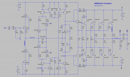
I think this is what you want Valery. I have to make some more adjustments, and add a D.C. servo, but is almost finished. I also am interest in test the output stage with the Damir voltage amplifier and another ones also. the capacitors and resistors at output can be modified depending on the voltage amplifier one uses.
PS: to make the output stage a more universal solution maybe the input buffer have to be different, I am afraid that if the input AC voltage is large enough it can damage the 2sk170, but I have to make additional tests to verify that.
PS: to make the output stage a more universal solution maybe the input buffer have to be different, I am afraid that if the input AC voltage is large enough it can damage the 2sk170, but I have to make additional tests to verify that.
Attachments
Last edited:
Yes, this is good. 2sk170 - yes, they may not survive the high swing... And there is not too much choice with regards to high-voltage jfets. I know some older options (like 2n5277, 2n5278 and 2n6449, 2n6450), but I don't think they are available these days...
What are you talking about? 2SK170 is cascaded thus protected from high voltage swing.
What are you talking about? 2SK170 is cascaded thus protected from high voltage swing.
OK. I was not attentive enough. All the high voltage is taken by DN2540. Excellent. I'm a king of "stupid mistakes", you know
BTW, the ones I can buy here are only DN2540N8 ones, meaning they've got TO-243AA case (SMD). We need to provide this option on the PCB.
Cheers,
Valery
The problem is that if one uses a voltage amplifier that can supply more than 45volts the 2sk170 will saturate and a current can pass in the gate to source junction , the maximum gate current is only 10ma. Maybe is better to use the buffer in the output of the voltage amplifier , will be better if one want to use the output stage in a different box like I am planning to do, the buffer on the output of the voltage amplifier will be of grate help in driving a cable.
OK. I was not attentive enough. All the high voltage is taken by DN2540. Excellent. I'm a king of "stupid mistakes", you know
BTW, the ones I can buy here are only DN2540N8 ones, meaning they've got TO-243AA case (SMD). We need to provide this option on the PCB.
Cheers,
Valery
Maybe a good compromise would be build a little pcb for the smd , like a to243 to to220 converter the smd part needs a relative large pad to dissipate the heat . What do you think ?
The problem is that if one uses a voltage amplifier that can supply more than 45volts the 2sk170 will saturate and a current can pass in the gate to source junction , the maximum gate current is only 10ma. Maybe is better to use the buffer in the output of the voltage amplifier , will be better if one want to use the output stage in a different box like I am planning to do, the buffer on the output of the voltage amplifier will be of grate help in driving a cable.
Maybe we can think about some protective clamping with the diodes? There are many front-ends with +/-50 - +/-70 V rails around here...
Maybe a good compromise would be build a little pcb for the smd , like a to243 to to220 converter the smd part needs a relative large pad to dissipate the heat . What do you think ?
Yes, this seems to be a good idea. Adapter can be mounted vertically, utilizing some small local heatsinks easily if required.
What dissipation level are we talking about? TO243 are less powerful than TO220 ones - let's just check if they are powerful enough...
I could calculate myself, but not sure about g-s offset (and therefore the quiescent current there)...
I think this is what you want Valery. I have to make some more adjustments, and add a D.C. servo, but is almost finished. I also am interest in test the output stage with the Damir voltage amplifier and another ones also. the capacitors and resistors at output can be modified depending on the voltage amplifier one uses.
PS: to make the output stage a more universal solution maybe the input buffer have to be different, I am afraid that if the input AC voltage is large enough it can damage the 2sk170, but I have to make additional tests to verify that.
HI
the 2SK246 could be better than 2SK170 for the buffer ?
Thanks
Yes, this seems to be a good idea. Adapter can be mounted vertically, utilizing some small local heatsinks easily if required.
What dissipation level are we talking about? TO243 are less powerful than TO220 ones - let's just check if they are powerful enough...
I could calculate myself, but not sure about g-s offset (and therefore the quiescent current there)...
Dissipation is going up to 700 mW in case of clipping if used with my ISP, so to220 is only option.
Dissipation is going up to 700 mW in case of clipping if used with my ISP, so to220 is only option.
OK. That means, I go to Mouser again
BTW, 2SK170 are not available in Mouser by some reason. But easily available locally here...
the DN2540 smd part can dissipate 1.6w , no problem. but the to220 is recommend.
2sk170 is obsolete and genuine parts are difficult to find, the ones that are available locally from you are provably fakes.
ONsemi have some smd jfets that can be perfect for this application.
http://www.onsemi.com/pub_link/Collateral/EN2841-D.PDF
2sk170 is obsolete and genuine parts are difficult to find, the ones that are available locally from you are provably fakes.
ONsemi have some smd jfets that can be perfect for this application.
http://www.onsemi.com/pub_link/Collateral/EN2841-D.PDF
HI
the 2SK246 could be better than 2SK170 for the buffer ?
Thanks
No. The Forward transfer admittance of 2SK246 is to low.
Do you really need the extra transistors Q41-42, would it not be possible to make current mirrors instead an simply mirror in the error correction current
I prefer independent current sources, not as D. Self is doing in his blamless, small transistors are cheap.
- Home
- Amplifiers
- Solid State
- GainWire-NGNFB-classB-PowerAmp