I prefer independent current sources, not as D. Self is doing in his blamless, small transistors are cheap.
Me too

Any type of current source will work in here, and of course current mirrors will be also good.Do you really need the extra transistors Q41-42, would it not be possible to make current mirrors instead an simply mirror in the error correction current
The current mirror that Damir choose uses a internal feedback loop that increase the output impedance , a desire feature in some aplications, but not of great importance in this particular case.
This afternoon if I have time , will also include here a circuit of the output stage that uses bootstrap power supply of the error correction and bias spreader stage. That way, only one power supply is needed.
I will fallow the Damir recommendation of leaving the buffer in the voltage amplifier stage.
This output stage has high input impedance but needs a low impedance source for the error correction to work, if someone wants to use it with a different input stage is important to make sure of that. A buffer with the two mosfets and the jfets can be adapted to your particular case , if someone need help on doing that I can try to help.
Hi
What do you think about this ?
http://www.diyaudio.com/forums/solid-state/258549-assemblage-power-amp-17.html#post4025507
What do you think about this ?
http://www.diyaudio.com/forums/solid-state/258549-assemblage-power-amp-17.html#post4025507
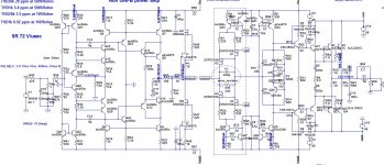
Hi Sergio, Damir - do we assume this schematic is close to final (plus DC servo)?
I'm going to spend some time on the layout...
Cheers,
Valery
I'm going to spend some time on the layout...
Cheers,
Valery
Valery, I will be away from home this weekend, so I may not make a lot of progress on the circuit. The circuit should work as it is, if you can not wait ") go ahead and design a pcb, it will at least serve to test the concept. You have to use a DC servo, and on the circuit were it says error_resistor you have to add a trim_pot in serie with that resistor.
go ahead and design a pcb, it will at least serve to test the concept. You have to use a DC servo, and on the circuit were it says error_resistor you have to add a trim_pot in serie with that resistor.
go ahead and design a pcb, it will at least serve to test the concept. You have to use a DC servo, and on the circuit were it says error_resistor you have to add a trim_pot in serie with that resistor.Hi Sergio, Damir - do we assume this schematic is close to final (plus DC servo)?
I'm going to spend some time on the layout...
Cheers,
Valery
Valery, there two a bit different OPSs. I used lower value power transistors emitter resistors and then a bit different compensation(RC between base - collector of the drivers instead simple capacitor), you can put a provision for that on the layout. Regarding thermal stability I prefer separate small heath sink for the drivers, and one transistor from the Vbe multiplier fixed to that heath sink, other to the main heath sink.
BR Damir
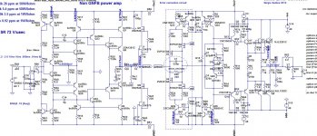
Here is NGNFB class B amp with Thermal Trak OPS, if someone prefer that way. I used this OPS in my TMC-TT amp so it is tested in real life. I will probably build that version as I have some spare Thermal Trak output transistors.
Dmir
Dmir
Attachments
Last edited:
You have to change transistors q33 to q36 , the current in the bias spreader seems a litle low. I also have some thermaltracking transistors , so i am ok with your circuit.
Oh yes I see it, it's now here. The Vbe multiplier should be a bit more simulated for thermal stability, but it could change some resistors value not the circuit, I hope.
Damir
Attachments
Hi Damir and all.
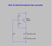
This weekend I have been focus on the thermal management of the output stage, and the best solution that I found for the thermaltrack transistors is the bias spreader that Bob Cordell advises in his book, the current sources have also to be changed, because it is important that the current on the bias spreader changes very little with temperature changes, will use the classical led ccs that has near zero tempco if a red ( AlInGaP ) led is use.
The Bob cordell solution is very simple but ingenious, and can be easily modify for work with normal 3 legs power transistors, Cordell also advises to use pré-drivers and drivers transistors on a separate heat-sink with a transistor to thermal compensate this transistors.
Will post the circuit tomorrow, as today I am very tired
Hi Damir and all.
This weekend I have been focus on the thermal management of the output stage, and the best solution that I found for the thermaltrack transistors is the bias spreader that Bob Cordell advises in his book, the current sources have also to be changed, because it is important that the current on the bias spreader changes very little with temperature changes, will use the classical led ccs that has near zero tempco if a red ( AlInGaP ) led is use.
The Bob cordell solution is very simple but ingenious, and can be easily modify for work with normal 3 legs power transistors, Cordell also advises to use pré-drivers and drivers transistors on a separate heat-sink with a transistor to thermal compensate this transistors.
Will post the circuit tomorrow, as today I am very tired
The bias spreader I used is devised from what Cordell suggested in his book (and I used it in my TMC-TT VFA amp). The current sources could be better true.
I was thinking to put one or even both bias spreader on the same separate heath sink with the drivers, I don't think that the pre drives need a heath sink.
Damir
By the way the diodes in the bias spreader transistors emitters are Thermal Trak diodes of course, and between drivers emitters too.
Last edited:
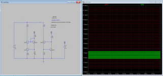
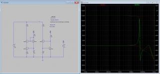
just want to show some differences between the led and the feedback ccs.
the first image is the variation of output current in a temperature change from 15º to 55º celcius, the led ccs is 160uA the feedback ccs is 1,3ma.
the second is the output impedance, the feedback ccs is a little better.
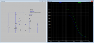
the last one is the frequency response, the feedback ccs is more prone to instability.
the first image is the variation of output current in a temperature change from 15º to 55º celcius, the led ccs is 160uA the feedback ccs is 1,3ma.
the second is the output impedance, the feedback ccs is a little better.
the last one is the frequency response, the feedback ccs is more prone to instability.
Attachments
just want to show some differences between the led and the feedback ccs.
the first image is the variation of output current in a temperature change from 15º to 55º celcius, the led ccs is 160uA the feedback ccs is 1,3ma.
the second is the output impedance, the feedback ccs is a little better.
the last one is the frequency response, the feedback ccs is more prone to instability.
The last one is not clear, where are those nodes? Is it 160 uA enough to drive the LED over the knee, in simulation probably it is?
The last one is not clear, where are those nodes? Is it 160 uA enough to drive the LED over the knee, in simulation probably it is?
The nodes are at Q2 and Q3 collectors. 160uA is the variation of output current with the change of ambient temperature from 15º to 55º celcius, the led current is near 1ma.
The bias spreader I used is devised from what Cordell suggested in his book (and I used it in my TMC-TT VFA amp). The current sources could be better true.
I was thinking to put one or even both bias spreader on the same separate heath sink with the drivers, I don't think that the pre drives need a heath sink.
Damir
By the way the diodes in the bias spreader transistors emitters are Thermal Trak diodes of course, and between drivers emitters too.
In the book I have his suggest this one,the extra resistor match the tempco of the sense diodes that are 1,7mv/cº to 2,1mv/cº of the transistor, is simple, but very effective.
The predrivers have to be mounted in the heat-sink, if they left out of the heatsink there is no thermal feedback from them, and a increase in temperature inside the amplifier case will increase the bias current of the output transistors, making the distortion increase.
Attachments
The nodes are at Q2 and Q3 collectors. 160uA is the variation of output current with the change of ambient temperature from 15º to 55º celcius, the led current is near 1ma.
Oh yes I see, the first picture, I didn't read carefully .
- Home
- Amplifiers
- Solid State
- GainWire-NGNFB-classB-PowerAmp