This is the constant chase to have the ultimate constant directivity, a never ending chase, it is just not a realistic phenomena. There is no perfect match that will ever create a true constant directivity. So you have to make real compromises that you can live with. If you could design the perfect device that matched to the waveguide you would still have the realistic problem of a finite length horn, that is the limitation that we all have to live with. As I said constant directivity is a semantic argument, it is not a realistic goal to think you can attain that across the entire bandwidth of any horn loaded device.
While I don't have polar plots for my system, I took 6 measurements of my right speaker across a 6' x 2' grid area at the listening position, basically across/front/back of a 3 seat couch:
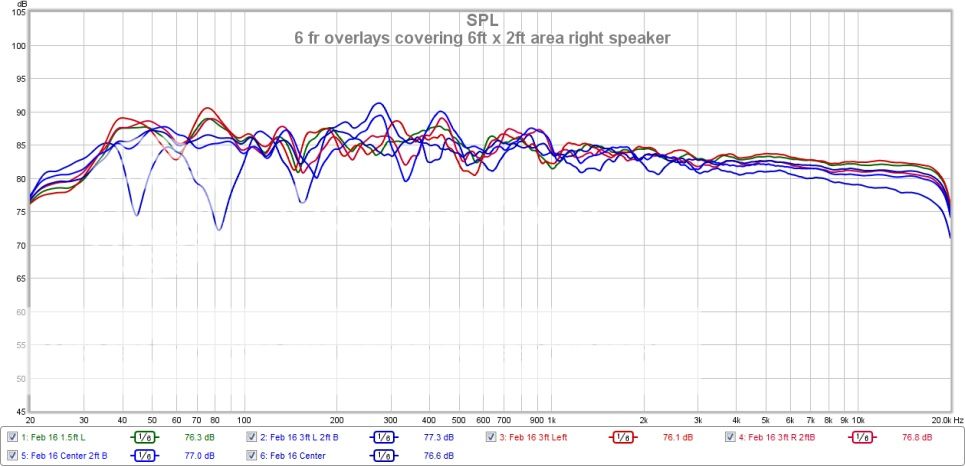
Looks fairly CD from 1kHz on up... I can flatten the frequency response to an even tighter tolerance by linearizing each driver, but its work and sounds pretty good as is sitting anywhere on my couch.
My triamp 3-way consists of a Crites 15" woofer in a large sealed cab, digital XO at 500 Hz to an old school Selenium D405 mated to JBL 2380a clone, digital XO at 5 kHz to a BMS 4540ND and mated to the QSC waveguide that was in the HPR152i.
I use Acourate for digital XO with 2nd order Neville Thiele filters and time aligned the drivers which produces a decent step response. I measured the individual drivers for distortion and zoomed in on the impulse response to see if there were any anomalies in the time domain. Could not really see anything notable.
Pretty happy with the SQ. Would love to try an OS waveguide and/or different compression driver on the mid-horn, but hesitant to spend as struggling with how much of an audible improvement there would be...?
Nice to know. Thanks.
What about the baffle to conic radius effect?
Handling the mouth in a waveguide is beyond the theory on which the waveguide is based. It must be dealt with in a separate theory. This is done analytically in my book and can be looked up there. But the bottom line is simple: Just make the radius as large as possible.
Nate - it would be a lot easier to analyze your waveguides if you provided a polar map. From that I might be able to comment.
PS. How do you make your waveguides? Fiberglass?
PSS. a constant radius from the throat to a conical section is the patented Quadratic Waveguide by Peavy. Not having as smooth a second derivative as the OS it will have more internal diffraction.
I'll get the data into a contour plot later today if I have time and post it here if that's cool with you. I have trouble seeing the detail I was describing though in a contour plot vs traditional fr plots. Maybe I'm just not that good at seeing those things in the contour plot.
Yeah, I make them in 'glass. I've made a couple rectangular mouth conical horns in wood and see the same effect at hf.
Diffraction is something I've wondered about with different contours. I don't have the math to prove one vs the other so I'll take your word for it there. Isn't this something that would be visible in the data though? Or is it a higher order thing?
Hi Nate
What I see people doing is very high resolution "traditional FR plots" and very low - smoothed - polar plots. Of course it is going to be hard to see in that case. But a high resolution polar plot is, to me, the ideal. It shows everything. Diffraction should show up in a hi-res polar map, or it isn't likely to be significant. Glass will not make a difference, it's just a pain to use (for me.)
Kindhornman - It seems to me that the inability of making something "perfect" is not a very good rational to ignore making it "optimum".
Earl,
It is not my intention to discourage anyone from trying to do their best and get things as good as they can. I just think the endless quest for perfect directivity is silly, you are never going to get it perfect so you should be able to be satisfied with a very smooth response curve and even directivity if that is your quest. But some seem to be on a quest for perfection and I don't think that is possible, it is no different than those who chase the under 1 PPM amplifier distortion numbers, there is a point where it is nothing but a quest for perfection that you can never reach. As you have looked at in the past there are levels of distortion or phase shifts that in real testing we just can't detect but some still make an issue of those factors. Some semblance of reality has to enter the picture and real attainable results need to be considered. Perfection will not happen with the current methods we have to convert electrical to mechanical motion to produce sound and that is where the reality seems to be lost in minutia.
It is not my intention to discourage anyone from trying to do their best and get things as good as they can. I just think the endless quest for perfect directivity is silly, you are never going to get it perfect so you should be able to be satisfied with a very smooth response curve and even directivity if that is your quest. But some seem to be on a quest for perfection and I don't think that is possible, it is no different than those who chase the under 1 PPM amplifier distortion numbers, there is a point where it is nothing but a quest for perfection that you can never reach. As you have looked at in the past there are levels of distortion or phase shifts that in real testing we just can't detect but some still make an issue of those factors. Some semblance of reality has to enter the picture and real attainable results need to be considered. Perfection will not happen with the current methods we have to convert electrical to mechanical motion to produce sound and that is where the reality seems to be lost in minutia.
I'd have thought so too, that with the right wavefront at the throat a cone continues a spherical sector of point source radiation. Yet there are modes within a cone. I'd also have thought that due to the symmetry of point source radiation the cone walls can be ruled out as the cause, and it must be due to local pressure differentials.A conic section is the only thing that can give a true constant directivity angle.
Do you think it's fair to conclude that point source radiation is also just a collection of modes? I'd have assumed an infinite number of modes so to speak (a continuum). All I can imagine is that the discrete appearance of these modes amounts to some kind of 'zooming in' on them in a practical conical, so I guess that's true. It could be the basis for one symptom based explaination for bandwidth limitations in a finite horn.
Still, optimizing is important.
If you are saying that other quests for the "perfect" waveguide are unlikely to better what is already out there, I agree. The NS-15 waveguide is highly optimized. I haven't seen anything that works better and that has been around for more than 20 years. (Of course all kinds of people will post non-comparable responses and claim they are better! We've seen that here numerous times.)
If you are saying that other quests for the "perfect" waveguide are unlikely to better what is already out there, I agree. The NS-15 waveguide is highly optimized. I haven't seen anything that works better and that has been around for more than 20 years. (Of course all kinds of people will post non-comparable responses and claim they are better! We've seen that here numerous times.)
AllenB - what can and cannot be done with the different "sections" in a waveguide is well covered in chapter 6 of my book. Since it is free online you really ought to read that chapter.
if that's cool with you.
Yea sure that's fine. But I would prefer to see them in my hi-res PolarMap database.
Yes Earl,
I think at best you can make minor changes that have very little end effect. Yes you can increase the end radius and change the bottom a little but how much better you can get the transition from the throat to the flare is questionable. It comes down to what type of polar response you really desire and how the room is treated at this point, I don't think we are going to see some breakthrough development in new horn shapes at this point. Perhaps some elliptical horn shapes that can also address the pattern flip that is common to a rectangular profile, or elliptical profile would be something to look at, basically an improved Bi-radial concept but I don't see much outside of that. Unless someone is going to make a compression driver as I thought of years ago and you patented in one of your patents where the phase plug is no longer just a round annular exit shape I don't know what else can be accomplished.
I think at best you can make minor changes that have very little end effect. Yes you can increase the end radius and change the bottom a little but how much better you can get the transition from the throat to the flare is questionable. It comes down to what type of polar response you really desire and how the room is treated at this point, I don't think we are going to see some breakthrough development in new horn shapes at this point. Perhaps some elliptical horn shapes that can also address the pattern flip that is common to a rectangular profile, or elliptical profile would be something to look at, basically an improved Bi-radial concept but I don't see much outside of that. Unless someone is going to make a compression driver as I thought of years ago and you patented in one of your patents where the phase plug is no longer just a round annular exit shape I don't know what else can be accomplished.
From the start I understood that a compression driver's exit angle is the issue to overcome, diffraction is the symptom leading to wider radiation, and OS is best at dealing with that. That it works, I chose to take in faith.It is not my intention to discourage anyone from trying to do their best and get things as good as they can. I just think the endless quest for perfect directivity is silly,
I like to carry on my own humble experiments in the lower midrange where I can forgo a little precision, plus I'm not sure I could do much better with my tweeters. I do have future plans though to begin rounding out the mouth earlier with a wider radius rather than holding the straight walls so far.
whgeiger prompted me to look further into phase plugs in the midrange, after which I built a pair of three slot round to ellipticals, and the same in axissymmetrical. The resulting sound seemed well worth the effort. Of course I change alot and they were painstaking to build.
I have a copy of your book, thank you Earl. I really should read it again in light of my changing understanding of the issues.AllenB - what can and cannot be done with the different "sections" in a waveguide is well covered in chapter 6 of my book. Since it is free online you really ought to read that chapter.
Does a spline mean changing radius?
What would be wrong with using a constant radius curve to transistion from the Throat angle to Conic sections angle?
What if the conic section were simplified to a cone?
And then constant radius curves?
Yes! And you want it change gradually, increasing away from the throat and decreasing towards the mouth; approaching conical in between. WHG
According to most research, the ears critical bandwidth is 1/6 octave. A couple examples are:
https://books.google.ca/books?id=t_...e&q=critical bands 1/6 octave hearing&f=false
and TEF 25 PROBLEMS!!! and TEF Subwoofer meaurements. from Tom Danley.
The 6 fr overlay graph in post 7362, while measured at high resolution, is displaying 1/6 octave smoothing, which visually matches our ears critical bandwidth audibility threshold. That's the correlation.
Displaying at higher resolution's than 1/6 octave can be misleading as our ears cannot audibly discriminate any narrower resolution. Increasing the measurement's graph visual resolution to display every narrow peak or valley, is not what our ears hear according to the research.
Earl, at what resolution do your PolarMap's display at?
Ok, here's some data I got in-room a couple weeks ago. There's a 3.8ms gate and the contour plots were created from that data which is 1/24octave smoothed. Data was taken in 10° steps from 0-90. The wg is eq'd to 20° which is the listening axis. The device in question is a 90x60 EOSwg for a BMS 4552nd 1" exit cd. It's 18" wide where the mouth roundover would be tangent to a baffle, but the roundover continues to roll back to 180deg (no baffle). The roundover is too small (1.625" r) which explains the narrowing pattern from 1-2khz. I created the horiz and vertical OS profile in SolidWorks, set the cd entrance and the elliptical mouth shape, and let SW interpolate the rest.
First are the fr curves, second is an ARTA contour plot (note this is 1/12 smoothed), and third is a contour plot I created in VACS. I've never used VACS on my own data so I'm sure I can optimize the view more. I made the scales on the contour plots the same but ARTA doesn't allow near the kind of options VACS does so in the ARTA plot you see 4dB steps and I set VACS for 3dB. 4dB steps in VACS wipes out too much detail. The VACS data looks much more coarse to me but I can't figure out how to make it any better. At any rate, you can see that the off-axis response is higher in level than the axial from 6-10khz. This is something I've seen in many waveguides,but as Kindhornman says maybe this is "good enough" and not enough to worry about. As a perfectionist I do want to get it as good as I can though.
I could send you the data, Earl, but I didn't use your angle convention and there is no time lock. The data I've sent you in the past had the time lock goofed up but you were still able to create a plot from that. If this is ok with you I can import the data to Holm and create the file set you need.
Attachments


Nathan,
So if I'm reading your post correctly you created a round to elliptical phase plug for a cone driver and then used an elliptical waveguide shape. I would be interested to see some pictures of that. I've even thought of using my current design starting from an elliptical cone shape and working out from there, something I haven't seen up to now.
So if I'm reading your post correctly you created a round to elliptical phase plug for a cone driver and then used an elliptical waveguide shape. I would be interested to see some pictures of that. I've even thought of using my current design starting from an elliptical cone shape and working out from there, something I haven't seen up to now.
KHman - nothing with a cone driver going on with these waveguides....maybe I misunderstand you. Here's the thread with the build details: http://www.diyaudio.com/forums/multi-way/258674-diy-18-elliptical-waveguide.html. Go to post 38 for the beginning of the construction of the wg I'm talking about. My methods are crude 🙄
Edit: looking back on my construction thread I see Earl needs data past 90° for his PolarMap. Doh!
Edit: looking back on my construction thread I see Earl needs data past 90° for his PolarMap. Doh!
Last edited:
Okay I see what you are doing now Nathan. A lofted pattern round to elliptical. I am a pattern maker by trade also so understand immediately what you are doing. Thanks for the link to your design. What is the ratio of width to height of your ellipse?
- Home
- Loudspeakers
- Multi-Way
- Geddes on Waveguides