HiHi Jag768
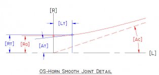
May this can help for calculating OS-WG horn profile:
Ro =driver throat radius
To = driver mouth exit angle
Te =coverage angle (form axis)
Then
ro = Ro*sqrt( 1 - [tan(To)/tan(Te)]^2)
Xo = Ro/tan(Te)*tan(To)/tan(Te)
y(x) = ro*sqrt( 1+ {[(x+Xo)/ro]*tan(Te)}^2), x={0……}
Regards
Ivica
To be 'compatible' with previous drawing
(RT) =driver throat radius
(AT)= driver mouth exit angle
(AC)=coverage angle (form axis)
Then
ro = RT*sqrt( 1 - [tan(AT)/tan(AC)]^2)
Xo = RT/tan(AC)*tan(AT)/tan(AC)
y(x) = ro*sqrt( 1+ {[(x+Xo)/ro]*tan(AC)}^2), x={0……}
Attachments
Insignificant
Considering the shallow angle between the adjoining front baffle and horn walls, the absence or size of a mouth radius is not going to be acoustically significant. Conversely, other details including enclosures boundaries and room placement, will be dominate variables in determining overall system performance at this point. Decreasing coverage angle and adding a mouth radius is a different story that may improve constant directivity over a wider frequency range.
Regards,
WHG
As I have remembered OSWG are of CD horn type, so mouth flare curve is not specified explicitly given but E.G. has suggested to be of semicircular flare whose radius is about Lamda/4, where Lamda corresponds to lowest usable frequency
Regards
Ivica
Considering the shallow angle between the adjoining front baffle and horn walls, the absence or size of a mouth radius is not going to be acoustically significant. Conversely, other details including enclosures boundaries and room placement, will be dominate variables in determining overall system performance at this point. Decreasing coverage angle and adding a mouth radius is a different story that may improve constant directivity over a wider frequency range.
Regards,
WHG
Last edited:
As I have remembered OSWG are of CD horn type, so mouth flare curve is not specified explicitly given but E.G. has suggested to be of semicircular flare whose radius is about Lamda/4, where Lamda corresponds to lowest usable frequency
Regards
Ivica
I have (AGAIN) made an error it has to be radius=Lamda/8
so it is better to see the figure
But here I want to emphasize that the loading of too large off-axis horn flare angled horn, would make very bad driver loading for lower frequency. I would suggest You to see the results from the:
http://www.diyaudio.com/forums/multi-way/103872-geddes-waveguides-717.html#post4062036
so over , say, 45 deg horn wall fare would suggest to use the driver may be over 2kHz.
Try to see the results from the famous 'HORNRESP' simulation program, and see the driver acoustical loading.
regards
ivica
Attachments
Last edited:
Notes
At the point at which the horn body and mouth lips are joined, the radii of curvature do not come close to matching, thus a geometric and acoustic discontinuity remains. Conventional horn theory as applied in this setting initially deals with horns where one end is finite end and the other is considered infinite to conveniently ovoid the issue of reflectance.
However horn theory also covers mouth shape and reflectance as well. A good example of this, may be found in the work of Benade on brass musical instrument design.
For finite loudspeaker horn design, a regime known as shape optimization may be used. Here a horn profile defined by a Bezier spline can be used to design a finite horn exhibiting radiating characteristics optimized for a particular application. It is important to note that such a spline can precisely follow the loci of all the conic sections as well, while avoiding the discontinuities that other approaches must sustain while transitioning between them.
Regards,
WHG
I have (AGAIN) made an error it has to be radius=Lamda/8
so it is better to see the figure
But here I want to emphasize that the loading of too large off-axis horn flare angled horn, would make very bad driver loading for lower frequency. I would suggest You to see the results from the:
http://www.diyaudio.com/forums/multi-way/103872-geddes-waveguides-717.html#post4062036
so over , say, 45 deg horn wall fare would suggest to use the driver may be over 2kHz.
Try to see the results from the famous 'HORNRESP' simulation program, and see the driver acoustical loading.
regards
ivica
At the point at which the horn body and mouth lips are joined, the radii of curvature do not come close to matching, thus a geometric and acoustic discontinuity remains. Conventional horn theory as applied in this setting initially deals with horns where one end is finite end and the other is considered infinite to conveniently ovoid the issue of reflectance.
However horn theory also covers mouth shape and reflectance as well. A good example of this, may be found in the work of Benade on brass musical instrument design.
For finite loudspeaker horn design, a regime known as shape optimization may be used. Here a horn profile defined by a Bezier spline can be used to design a finite horn exhibiting radiating characteristics optimized for a particular application. It is important to note that such a spline can precisely follow the loci of all the conic sections as well, while avoiding the discontinuities that other approaches must sustain while transitioning between them.
Regards,
WHG
Hi whgeiger,
I only wonder is it easy to apply "shape optimization" in DIY approach horn design.
Here, in order to "softly" transform horn wall flare from almost "conical" section to baffle surface, may be JMMLC iterative approach of horn wall flare can be used, as it can be applied in EXCEL.
Regards
Ivica
Hi whgeiger,
But many thanks for the paper You have posted us:
http://www.diyaudio.com/forums/multi-way/103872-geddes-waveguides-740.html#post4458948
http://www.diyaudio.com/forums/atta...2853569-geddes-waveguides-200942733837187.pdf
Regards
Ivica
But many thanks for the paper You have posted us:
http://www.diyaudio.com/forums/multi-way/103872-geddes-waveguides-740.html#post4458948
http://www.diyaudio.com/forums/atta...2853569-geddes-waveguides-200942733837187.pdf
Regards
Ivica
Hi whgeiger,
I only wonder is it easy to apply "shape optimization" in DIY approach horn design.
Regards
Ivica
There was a guy who did his PhD thesis on shape optimization of a waveguide contour, but this was a major piece of work using very complex procedures. The result confirmed that an OS waveguide with a mouth flare is extremely close to what he found to be "optimum". The differences, to me, were insignificant and since using an OS contour is so easy, why would one not go this route?
I wish that I had the link to the AUS thesis, but not readily.
A good example of this, may be found in the work of Benade on brass musical instrument design.
Regards,
WHG
Benade's work has limited applicability to the discussion here. He considered only the lowest mode of propagation and was interested only in the impedances that result from a mouth termination (to find predicted resonances of the devices.) His approach works well for impedance calculations but lacks a well defined specification of the wave front shape, which is essential to find the directivity. Benade never considered directivity and from my reading of his approach could not have calculated the directivity of the devices that he studied.
I wish that I had the link to the AUS thesis, but not readily.
Thesis:
https://digital.library.adelaide.edu.au/dspace/handle/2440/41350
Paper:
http://data.mecheng.adelaide.edu.au...s/2008/preprint_morgans_optimization_2008.pdf
Yes but ....
Earl,
... that is not the issue I raised when the work of Benade was referenced by me concerning horn reflectance.
So, I take issue with your assertions in this regard:
1) “Mouth flare is never part of any horn/waveguide theory, they all deal with devices of infinite extent.”
Of course musical instrument horn design has priorities different than those of loudspeakers horns. Nevertheless, theory exists to deal with the issue of reflectance introduce by a finite horn that is essentially independent of its directivity.
2) “The differences, to me, were insignificant and since using an OS contour is so easy, why would one not go this route?”
As you well know, what is happening inside a horn is not simple. And the horn that emerges from conventional design regimes, requires many hours of tweaking in the acoustics lab to get close to an optimized design.
Additionally the geometry is markedly different than that emerging from a shape optimization regime.
Here for wide-band applications, complete horn profiles are generated whose radii of curvature increases away from the throat end and then decreases as the mouth end is approached without introducing discontinuities in the resulting curve’s second derivative.
I suspect that eventually this profile [1] will be characterized by a set of parameters that will simplify its application to loudspeaker horn design by scaling them to fit the wavelengths to be passed, at some reasonable radiation angle that allows the horn to perform its intended function.
In the meantime, let the computer do the ‘grunt work’ when COMSOL [3] or similar resources [4], [5], [6], [7], [8] & [9] are available in computerized form.
For those readers that are interested in pursuing alternative horn design regimens, the following references are provided. These are just a few of what is commercially available. Maybe David McBean has, will, or is about to, implement some of these design features in his program as well.
[1] Typical Optimized Profile of an Axisymmetric Horn
See attached files: MorgansFigs9&10.pdf
[2] EGO shape optimization of horn loaded loudspeakers
See Attached File MorgansOpt df
df
[3] Optimization using COMSOL
https://www.comsol.com/model/optimizing-the-shape-of-a-horn-4353
https://www.comsol.com/paper/download/62916/salvatti_presentation.pdf
[4] U.S. Patent: Method of designing a sound waveguide surface
See attached File 8494815.pdf
[5] Tools for the Professional Development of Horn Loudspeakers
http://publications.rwth-aachen.de/record/61507/files/Makarski_Michael.pdf
[6] Shape Optimization for Acoustic Wave Propagation Problems
http://uu.diva-portal.org/smash/get/diva2:286603/FULLTEXT01.pdf
[7] Simulation of Horn Driver Response by Direct Combination of Compression Driver Frequency Response and Horn FEA
See attached file Cinanni.pdf
[8] SpeakerLab Software
SpeakerLAB srl
[9] Horn.ell.a YouTube Tutorial
https://www.youtube.com/watch?v=AqKZ4S-yh38
Regards,
Bill
Benade's work has limited applicability to the discussion here. He considered only the lowest mode of propagation and was interested only in the impedances that result from a mouth termination (to find predicted resonances of the devices.) His approach works well for impedance calculations but lacks a well defined specification of the wave front shape, which is essential to find the directivity. Benade never considered directivity and from my reading of his approach could not have calculated the directivity of the devices that he studied.
Earl,
... that is not the issue I raised when the work of Benade was referenced by me concerning horn reflectance.
So, I take issue with your assertions in this regard:
1) “Mouth flare is never part of any horn/waveguide theory, they all deal with devices of infinite extent.”
Of course musical instrument horn design has priorities different than those of loudspeakers horns. Nevertheless, theory exists to deal with the issue of reflectance introduce by a finite horn that is essentially independent of its directivity.
2) “The differences, to me, were insignificant and since using an OS contour is so easy, why would one not go this route?”
As you well know, what is happening inside a horn is not simple. And the horn that emerges from conventional design regimes, requires many hours of tweaking in the acoustics lab to get close to an optimized design.
Additionally the geometry is markedly different than that emerging from a shape optimization regime.
Here for wide-band applications, complete horn profiles are generated whose radii of curvature increases away from the throat end and then decreases as the mouth end is approached without introducing discontinuities in the resulting curve’s second derivative.
I suspect that eventually this profile [1] will be characterized by a set of parameters that will simplify its application to loudspeaker horn design by scaling them to fit the wavelengths to be passed, at some reasonable radiation angle that allows the horn to perform its intended function.
In the meantime, let the computer do the ‘grunt work’ when COMSOL [3] or similar resources [4], [5], [6], [7], [8] & [9] are available in computerized form.
For those readers that are interested in pursuing alternative horn design regimens, the following references are provided. These are just a few of what is commercially available. Maybe David McBean has, will, or is about to, implement some of these design features in his program as well.
[1] Typical Optimized Profile of an Axisymmetric Horn
See attached files: MorgansFigs9&10.pdf
[2] EGO shape optimization of horn loaded loudspeakers
See Attached File MorgansOpt
df[3] Optimization using COMSOL
https://www.comsol.com/model/optimizing-the-shape-of-a-horn-4353
https://www.comsol.com/paper/download/62916/salvatti_presentation.pdf
[4] U.S. Patent: Method of designing a sound waveguide surface
See attached File 8494815.pdf
[5] Tools for the Professional Development of Horn Loudspeakers
http://publications.rwth-aachen.de/record/61507/files/Makarski_Michael.pdf
[6] Shape Optimization for Acoustic Wave Propagation Problems
http://uu.diva-portal.org/smash/get/diva2:286603/FULLTEXT01.pdf
[7] Simulation of Horn Driver Response by Direct Combination of Compression Driver Frequency Response and Horn FEA
See attached file Cinanni.pdf
[8] SpeakerLab Software
SpeakerLAB srl
[9] Horn.ell.a YouTube Tutorial
https://www.youtube.com/watch?v=AqKZ4S-yh38
Regards,
Bill
Attachments
Jag768 - here's a link to johnk's spreadsheet which allows you to set the entrance angle. This is what I use for my builds: http://www.musicanddesign.com/codes/OS_wave_guide.zip
There are certainly a lot of advancements in waveguide design with computers in the last 20 years via FEA and BEM - techniques not effective when I studied the problem. But yet, I have not seen anything that improves upon the classic OS design.
"[4] U.S. Patent: Method of designing a sound waveguide surface
See attached File 8494815.pdf"
Despite being a nice technique, it is basically exactly what every designer has done since the beginning (or at least as long as one has cared about directivity; for me some 30 years,) maybe not ALL by a computer, but the same process none the less. Fortunately the patent would be impossible to enforce unless someone was dumb enough to actually admit to doing this in practice.
Reply
Earl,
My purpose was to give readership here some exposure to the results of my current research on horn design. There is a lot more out there but the documentation is held hostage by the publishers. For that outside ASA & AES, I just refuse to pay $30+ for a $5 article no matter how good it may be as the expected probabilities of real discovery are far too small as you point out. As far as the patent goes, there simply too much prior art out there to permit enforcement even for a case of infringement brought against a horn design software development effort. I think after several strategically selected cases were simulated, for Morgan's profile, a deterministic methods could be devised to fill in the blanks between and eliminate all the future processing time now required.
Regards,
Bill
There are certainly a lot of advancements in waveguide design with computers in the last 20 years via FEA and BEM - techniques not effective when I studied the problem. But yet, I have not seen anything that improves upon the classic OS design.
"[4] U.S. Patent: Method of designing a sound waveguide surface
See attached File 8494815.pdf"
Despite being a nice technique, it is basically exactly what every designer has done since the beginning (or at least as long as one has cared about directivity; for me some 30 years,) maybe not ALL by a computer, but the same process none the less. Fortunately the patent would be impossible to enforce unless someone was dumb enough to actually admit to doing this in practice.
Earl,
My purpose was to give readership here some exposure to the results of my current research on horn design. There is a lot more out there but the documentation is held hostage by the publishers. For that outside ASA & AES, I just refuse to pay $30+ for a $5 article no matter how good it may be as the expected probabilities of real discovery are far too small as you point out. As far as the patent goes, there simply too much prior art out there to permit enforcement even for a case of infringement brought against a horn design software development effort. I think after several strategically selected cases were simulated, for Morgan's profile, a deterministic methods could be devised to fill in the blanks between and eliminate all the future processing time now required.
Regards,
Bill
It has been a long time since I did anything theoretical in waveguide design - maybe 10 years or more. Hence, I am way out of the loop on the most recent advancements in technique. But from what I have seen not much has really been progressed - certainly, what would be the point! We have virtually all the answers now - its just a matter of follow through. I certainly believe that "there are many ways to skin a cat" and there will be more ways to achieve CD. I found one, it works well, I'll stick with that.
Hi
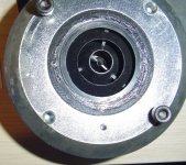
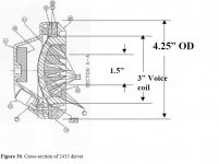
I am curious to try a larger OS with JBL 2435h (actually 90x60 EOS). Can someone please assist determine the optimum WG entrance angle to be used with this CD?
For information I have attached a picture (taken from Robh3606 at audioheritage) of the phase plug and a cross-sectional drawing from JBL.
I am curious to try a larger OS with JBL 2435h (actually 90x60 EOS). Can someone please assist determine the optimum WG entrance angle to be used with this CD?
For information I have attached a picture (taken from Robh3606 at audioheritage) of the phase plug and a cross-sectional drawing from JBL.
Attachments
Thank you for your generosity. You lead the way in a resurgence of homebrew loudspeakers that approach live music for dynamics, tone and dare we say - musicality.It has been a long time since I did anything theoretical in waveguide design - maybe 10 years or more. Hence, I am way out of the loop on the most recent advancements in technique. But from what I have seen not much has really been progressed - certainly, what would be the point! We have virtually all the answers now - its just a matter of follow through. I certainly believe that "there are many ways to skin a cat" and there will be more ways to achieve CD. I found one, it works well, I'll stick with that.
Kudos
Sent from my Nexus 6 using Tapatalk
Not what you sespect.
Tie angle will be negative and to the left of the apex given the horn mouth on the right, If you need a sketch I can provide. WHG
Hi
I am curious to try a larger OS with JBL 2435h (actually 90x60 EOS). Can someone please assist determine the optimum WG entrance angle to be used with this CD?
For information I have attached a picture (taken from Robh3606 at audioheritage) of the phase plug and a cross-sectional drawing from JBL.
Tie angle will be negative and to the left of the apex given the horn mouth on the right, If you need a sketch I can provide. WHG
Bill is correct, the angle will be negative and this poses some issues. One will have to do a reverse OS contour to some section with zero slope and then an OS which starts at a zero slope. The effect that this will have on performance is unknown, but I would not expect it to be good.
One could - and this is what I would do - assume that the wavefront at the exit aperture is flat (which is not very likely, but it is likely that this was the design intent). Then one would just use an OS contour with zero slope at its entrance.
Either way, this is not a good driver choice for an OS waveguide.
- Home
- Loudspeakers
- Multi-Way
- Geddes on Waveguides