Thanks whgeiger that's very generous of you. I'm using an Excel spreadsheet for the profile (based on the spreadsheets previously made available by Gedde). I only have to include a round-over to the mouth before I can say it's complete. If you're willing to approbate it when finished, I'd be grateful. Always better to have two set of eyes ")
You have confirmed my suspicion with the negative angle. The pase plug however do not use fixed angle for the slits. Do you know the optimum WG entrance angle to use with this CD? I believe it would be a compromise regardless?
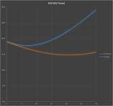
BTW, to my understanding the throat profile lines (vertical + horizontal) would look something like the figure below - example with -15deg entrance for the purpose of illustration
You have confirmed my suspicion with the negative angle. The pase plug however do not use fixed angle for the slits. Do you know the optimum WG entrance angle to use with this CD? I believe it would be a compromise regardless?
BTW, to my understanding the throat profile lines (vertical + horizontal) would look something like the figure below - example with -15deg entrance for the purpose of illustration
Attachments
I believe so, the intention from JBL was to create a plane wave front. This kind of aperture is the way JBL have made their latest series of large format CDs - optimized for their waveguides. I would be surprised if they did not measure descent in an OS/EOS profile. I have a pair of 15" EOS made for 1,4" exit drivers. With the 2435 aperture it should not be much of a trade off to mount it to the 1,4" for a quick and dirty testBill is correct, the angle will be negative and this poses some issues. One will have to do a reverse OS contour to some section with zero slope and then an OS which starts at a zero slope. The effect that this will have on performance is unknown, but I would not expect it to be good.
One could - and this is what I would do - assume that the wavefront at the exit aperture is flat (which is not very likely, but it is likely that this was the design intent). Then one would just use an OS contour with zero slope at its entrance.
Either way, this is not a good driver choice for an OS waveguide.
I believe so, the intention from JBL was to create a plane wave front.
If you know that to be true, then you would not want to use a reverse flare from the exit aperture. The initial angle would just be taken as 0. But with the channels being connected to the aperture at various angles, the wave-front cannot be perfectly flat. What it actually looks like is anybody's guess.
I do not know if this is true other than what I have found when trawling the various forums. I cannot find an exact statement by JBL that this is truly a plane wavefront. From JBL's technical note regarding 2451 (same kind of aperture) they say;
http://www.diyaudio.com/forums/atta...leach-horns-jbl-s-new-optimized-aperture-.pdf
However when looking at the shape of the phase plug, I was leaded towards the thought of using negative entrance angle.
whgeiger; have you made any experience with the 2435 in OS WG?
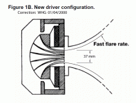
By our calculations, the initial flare rate in the older
driver design was approximately 160 Hz, reflecting the
need to drive the very large horns that were used in
early motion picture systems. Today, we can double or
quadruple that flare rate, inasmuch as many horns are
now intended for nominal crossover at 800 Hz.
Rapid flare rates offer an opportunity to make
improvements in high frequency pattern control. Since
the exit of the phasing plug is virtually at the apex of
the horn, there is normally an excellent sight line into
the phasing plug, even at the extremes of angular
coverage; this is virtually a guarantee that high
frequency signals will illuminate the entire wave guide
and show little tendency to beam on axis.
http://www.diyaudio.com/forums/atta...leach-horns-jbl-s-new-optimized-aperture-.pdf
However when looking at the shape of the phase plug, I was leaded towards the thought of using negative entrance angle.
whgeiger; have you made any experience with the 2435 in OS WG?
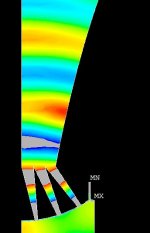
I reverse engineered one of my 2435's a long time and did some fully coupled finite element modeling of it on the horn I was designing for it. The model matched the measured directivity pretty well. What I saw in the model was that the wave front was pretty flat at the exit of the phase plug up to about 9kHz (shown below). Above there it gets a bit messy and that's where the directivity of my horn gets messy. I crossover to a smaller horn above there to control the directivity of the system.
Attachments
Hi
I am curious to try a larger OS with JBL 2435h (actually 90x60 EOS). Can someone please assist determine the optimum WG entrance angle to be used with this CD?
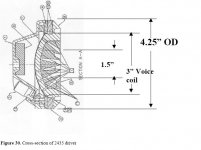
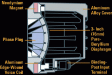
For information I have attached a picture (taken from Robh3606 at audioheritage) of the phase plug and a cross-sectional drawing from JBL.
Hi Tytte71,
I would start from zero angle, as I expect that JBL has trying to produce almost flat wavw front at the driver exit. Even a short (less then half of inch) pure tubular shape can be assumed, and after that proper (??) cross section surface flare woul be welcome .
Proper mouth curvature would be importace too.
If you would like to get good dispersion over 10kHz, a kind of stencil has to be applied in the horn throat, as it can be shown on M2, 238x,..
Regarding
Ivica
If you would like to get good dispersion over 10kHz, a kind of stencil has to be applied in the horn throat, as it can be shown on M2
Ivica
Could you elaborate?
I get very good control over 10 kHz with my DE500 drivers, so it's not a given that this needs correction. It would appear that it is a problem with the drivers phase plug, which I would suggest is seldom done correctly.
Simulation Questioned for 2-Reasons:
1) Where the boundary of the outer phase plug annulus joins the horn throat, a diffraction edge is presented, but no wave diffraction at this edge may be observed in the simulation.
2) The volume velocities of the individual phase plug passages are not equal, and their vectors are not normal to the phase plug plane of exit; so formation of a plain wave across that surface, or in its immediate vicinity, is not possible.
Regards,
WHG
I reverse engineered one of my 2435's a long time and did some fully coupled finite element modeling of it on the horn I was designing for it. The model matched the measured directivity pretty well. What I saw in the model was that the wave front was pretty flat at the exit of the phase plug up to about 9kHz (shown below). Above there it gets a bit messy and that's where the directivity of my horn gets messy. I crossover to a smaller horn above there to control the directivity of the system.
1) Where the boundary of the outer phase plug annulus joins the horn throat, a diffraction edge is presented, but no wave diffraction at this edge may be observed in the simulation.
2) The volume velocities of the individual phase plug passages are not equal, and their vectors are not normal to the phase plug plane of exit; so formation of a plain wave across that surface, or in its immediate vicinity, is not possible.
Regards,
WHG
2) The volume velocities of the individual phase plug passages are not equal, and their vectors are not normal to the phase plug plane of exit; so formation of a plain wave across that surface, or in its immediate vicinity, is not possible.
Seems like I read this somewhere ... Oh yea, it's in my patent!
I reverse engineered one of my 2435's a long time and did some fully coupled finite element modeling of it on the horn I was designing for it. The model matched the measured directivity pretty well. What I saw in the model was that the wave front was pretty flat at the exit of the phase plug up to about 9kHz (shown below). Above there it gets a bit messy and that's where the directivity of my horn gets messy. I crossover to a smaller horn above there to control the directivity of the system.
If the phase plug pictured is what you modeled, it is incorrect. The paths through the plug segments on the 2435's are curved, even the center one is slightly, the outer one the most.
Barry.
Diligent Student
of your work as well as that of others. Bill
Seems like I read this somewhere ... Oh yea, it's in my patent!
of your work as well as that of others. Bill
Last edited:
If the phase plug pictured is what you modeled, it is incorrect. The paths through the plug segments on the 2435's are curved, even the center one is slightly, the outer one the most.
Barry.
I did not disassemble my driver completely, just measured the start and end dimensions of the plug. Visually I could not see any curve. I just found the attached diagram of a 2435. If it's correct, it looks like there are some very slight curves to the insides of the slots, but the outer one has the least curve. When I overlay straight lines, I see some slight deviation. Did you disassemble a 2435? Are you sure you're not thinking of a 2450?
Attachments
Hi ivicaiHi Tytte71,
I would start from zero angle, as I expect that JBL has trying to produce almost flat wavw front at the driver exit. Even a short (less then half of inch) pure tubular shape can be assumed, and after that proper (??) cross section surface flare woul be welcome .
Proper mouth curvature would be importace too.
If you would like to get good dispersion over 10kHz, a kind of stencil has to be applied in the horn throat, as it can be shown on M2, 238x,..
Regarding
Ivica
JBL mates these pancake drivers to horns equipped with what they call optimized apertures. Also when used in line arrays they terminate the drivers to a waveguide for which they claim to produce a coherent wavefront. Unfortunately I can not find any documentation explaining their meaning of the terms nor documenting its properties. But it is reason to believe that they have aimed at plane wavefront.
I do want to avoid introducing any kind of diffraction device as such device will be a gamble. I have also seen measurements done on the M2 with 2435 and the combo starts beaming just above 10kHz. However, on-axis response is remarkable flat/linear until mass break set in. The top-end on-axis fall off is a little steeper than desirable. I am prepared to use a tweeter, but would also optimize the WG for this CD.
JBL 2447 & 2451 CDs [1] ....
have coherent wave front phase plugs as well as the 476Be & 045be-1 [2].
There may be others.
See attached drawing. WHG
I did not disassemble my driver completely, just measured the start and end dimensions of the plug. Visually I could not see any curve. I just found the attached diagram of a 2435. If it's correct, it looks like there are some very slight curves to the insides of the slots, but the outer one has the least curve. When I overlay straight lines, I see some slight deviation. Did you disassemble a 2435? Are you sure you're not thinking of a 2450?
have coherent wave front phase plugs as well as the 476Be & 045be-1 [2].
There may be others.
See attached drawing. WHG
Attachments
I did not disassemble my driver completely, just measured the start and end dimensions of the plug. Visually I could not see any curve. I just found the attached diagram of a 2435. If it's correct, it looks like there are some very slight curves to the insides of the slots, but the outer one has the least curve. When I overlay straight lines, I see some slight deviation. Did you disassemble a 2435? Are you sure you're not thinking of a 2450?
The ones I had apart were the 2435Be drivers.
The one you have pictured looks like a pro model ? judging by the back cap being very different than the Be and Al rear caps, and may very well have a straight path phase plug. I have never had any other 2435's apart.
I assumed they were all the same. Always a big mistake! Sorry.
Barry.
The 2435Al's in my 1400 Arrays look from the front of the horn to be the same as the Be's but I have not had them apart and it's hard to really be sure.
Hi Barry.The ones I had apart were the 2435Be drivers.
The one you have pictured looks like a pro model ? judging by the back cap being very different than the Be and Al rear caps, and may very well have a straight path phase plug. I have never had any other 2435's apart.
I assumed they were all the same. Always a big mistake! Sorry.
Barry.
The 2435Al's in my 1400 Arrays look from the front of the horn to be the same as the Be's but I have not had them apart and it's hard to really be sure.
I suppose you have looked at the 435 driver supplied with Array 1400 and not 2435, the pro version of 435?
The cross sectional drawing of 435's indicates that 435 and 2435 uses the same phase plug geometry.
Attachments
Details
These are some of the JBL CDs that are candidates to drive an OS horn. Of course, others may be used as well, but some level of degraded performance will have to be sustained when doing so. Whether it will be important in a particular application is unknown. WHG
The figure shown is a corrected version from this JBL Tech Note:
http://www.diyaudio.rs/JBL/JBL Technical Note - Vol.1, No.21.pdf
Bill, If the cross sectional drawing of 2435 is a JBL original then it seems like 2451 is quite different from 2435.
These are some of the JBL CDs that are candidates to drive an OS horn. Of course, others may be used as well, but some level of degraded performance will have to be sustained when doing so. Whether it will be important in a particular application is unknown. WHG
The figure shown is a corrected version from this JBL Tech Note:
http://www.diyaudio.rs/JBL/JBL Technical Note - Vol.1, No.21.pdf
Last edited:
- Home
- Loudspeakers
- Multi-Way
- Geddes on Waveguides