You will need an electronic correction filter that depends on the characteristics of the loudspeaker (assuming you stay out of KSTR's jump resonance regime). I guess that makes it more difficult to combine amplifiers and loudspeakers.What are the economic disadvantages if current drive is used instead of voltage drive? I am asking this non-technical question because many decisions in the manufacturing industry are based on financial gain/profit. In other words, does it cost more or less for the industry?
Of course the logical thing to do with an amplifier is to put it inside the loudspeaker. It gives a lot of design freedom: you can use whatever driving impedance you like, whatever equalization you want, and even motional feedback becomes possible. Active loudspeakers never got popular, though, until the advent of active computer loudspeakers, Bluetooth loudspeakers and things like that.
Current drive was used a lot in valve radios, sometimes with a cloth behind the speaker to reduce the mechanical Q.
Until KSTR came with the jump resonance paper, it didn't do any harm at low frequencies, it just wasn't that effective in reducing distortion as it was at higher frequencies.I am so lost sometimes in discussions.
It was already clear that it doesn't work well for lower frequencies.
See and read the papers posted earlier.
So Q-factor is totally not a thing anymore?
Can we move on from that please?
clear that it doesn't work well for lower frequencies
Only if their is a rise in loudspeaker imoedance at resonance. If it is flat a current drive amo works fine. Elsinore Mk6 is a rare example of such a loudspeaker. He has a brute force electrical bit in the XO (could be called EQ i guess).
The big issue is that after some 4 decades after turning right (as Nelson portrays it), most loudspeakers & drivers for loudspeakers assume a voltage amplifier.
If one can find a driver with low Qm one can get pretty close to a flat impedance with something like an aperiodic TL.
If yourloudspeaker has flat impedance it does not really matter, FR-wize, what the amplifier Rout is.
dave

It is not hard to design an amp with very high Zout
No feedback pentode amplifier for instance.
Like this one. I didn’t know it at the time, it is a rebuild based on the amplifier in my parents “stereo” with the fold down TT. Back when i was just learning something about tubes. Allen Wright helped a bit (and named it).
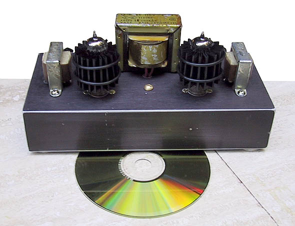
https://www.t-linespeakers.org/tubes/SEP_50EH5.html
dave
Over 7 decades actually. The turning point: Wilchur's boxed speakers and Williamson's amplifier with global negative feedback.The big issue is that after some 4 decades after turning right (as Nelson portrays it), most loudspeakers & drivers for loudspeakers assume a voltage amplifier.
There was a decade and a half (from 1934 to early 1950s when no-NFB pentode amplifiers were mainstream commercial topology. Speakers were low Qms in open boxes, they didn't require electric damping. People who cared about fidelity (the concept of high fidelity was introduced in mid-30s) were happy with the sound.No feedback pentode amplifier for instance.
Like this one. I didn’t know it at the time, it is a rebuild based on the amplifier in my parents “stereo” with the fold down TT. Back when i was just learning something about tubes. Allen Wright helped a bit (and named it).
https://www.t-linespeakers.org/tubes/SEP_50EH5.html
dave
Do you mean an impedance correction network or something else? A loudspeaker with an LRC series network shunted across it driven from an amplifier with current output would effectively have mixed drive: driving impedance R at resonance, large far from resonance.Only if their is a rise in loudspeaker imoedance at resonance. If it is flat a current drive amo works fine. Elsinore Mk6 is a rare example of such a loudspeaker. He has a brute force electrical bit in the XO (could be called EQ i guess).
Regarding passive crossovers, you can design those for current drive. Of course the admittance of the crossover components will spoil the current drive to some extent, just like the impedance of the crossover components does with voltage drive.
If I didn't make any mistakes, the upper part is a voltage second-order Linkwitz-Riley crossover and the bottom part its dual, a current second-order Linkwitz-Riley crossover. Substitute G = 1/R and you see that the inductances are four times smaller and the capacitances four times larger for the current version.

If I didn't make any mistakes, the upper part is a voltage second-order Linkwitz-Riley crossover and the bottom part its dual, a current second-order Linkwitz-Riley crossover. Substitute G = 1/R and you see that the inductances are four times smaller and the capacitances four times larger for the current version.
Hello Jan,That's what I thought. We know that with a voltage drive amp, the output impedance determines how well the EMF is absorbed by the amp so as to damp the speaker motion resulting from its own resonance. Damping factor - and ideally the output impedance is zero so the speaker EMF is 100% absorbed and the speaker tightly damped.
With current drive, the output impedance is (ideally) infinite and there is no damping of the speaker movement by absorbing the EMF.
You can see this in for instance how the speaker freq response follows the speaker impedance response, necessitating (sp?) response equalisation.
A speaker under current drive will ring like a bell when excited mechanically. The same when excited electrically due to for instance a transient signal.
No?
Jan
I'm not sure if amplifier absorbs EMF, I'm not too familiar with how amplifiers actually work so I'm not sure 😀 But the EMF is physics and explained without amplifier at all so I'll resort to that. The electromagnetic and mechanic device loudspeaker driver we inspect Electro Magnetic Force works both ways, as motor and generator. There is stationary magnet and associated magnetic field, then we have a moving coil. When there is current in the coil it moves, and when it moves there is voltage induced in the coil and if its a closed circuit then there is current that makes magnetic field that opposes the movement ( https://en.wikipedia.org/wiki/Lenz's_law ), hense the name back-EMF. This is how all generators work for example, how we can extract electric power from movement, or any electric motor, same device just used backwards.
Well, anyway, there is this back-EMF voltage between driver terminals due to moving cone no matter what makes it move, poking it with a finger, standing wave in closed box enclosure or our power amplifier. Back-EMF is flip side of the very same physical phenomenon that allows amplifiers to make the cone move in the first place, something we always have with such transducer technology.
About damping, there is more detail in Esa's article, book, search engines find even more, but basically when the cone moves back-EMF voltage makes current in the circuit and the current should make opposing magnetic field which opposes the movement, dampens it. This happens in drivers resonance but the twist is that higher up in frequency the back-EMF voltage made current has phase lag to it due to mass in the moving system (as I understood) and the induced current does not have any damping effect anymore due to phase shift. The current could go even past 90 degree phase difference because of increasing inductance in the circuit and could even magnify the movement instead of damping it.
I think this article is very good read and explains it nicely, not too tough, simple math and explanations. For the above explanation skip to title "The assumed control of cone motion" https://www.edn.com/loudspeaker-operation-the-superiority-of-current-drive-over-voltage-drive/
To sum it up, back-EMF voltage is always there on moving coil transducer and we can do nothing about it, its result of the movement of the cone. If impedance of circuit is low enough also current flow results. Depending on frequency this current can be useful (damping of resonance) but due to non-linear properties of motor its mostly detrimental (distortion). Thinking it through like this the amplifiers contribution to all of it is merely what the output impedance of it is in the circuit, how it affects load the back-EMF voltage sees, what current results, if features of the back-EMF become acoustic or not.
Radically thinking, low output impedance of voltage amp allows driver to damp itself at resonance but also allows it to emit its own distortion maximally into acoustic domain. Increasing impedance in the circuit, like introducing a current amplifier or other series impedance, prevents driver to dampen itself at resonance but also prevents this non-linear motor back-EMF to make into acoustic domain.
Last edited:
I'd say it totally spoils the idea. Typically, the woofer would like to see high source impedance at the end of its passband and tweeter would like to see high impedance at the start of its passband for maximum benefit.Regarding passive crossovers, you can design those for current drive. Of course the admittance of the crossover components will spoil the current drive to some extent
I have Esa's book, have read it several times. I have mixed feelings about it.
To give an example of the misleading things written, look at this:
"The most remarkable thing here regarding loudspeakers is that the voltage between the ends of the wire does not appear anywhere in these equations. That is, the speaker driver in the end obeys only current, not caring what the voltage across the terminals happens to be."
The big elephant here is that you need voltage to get current to flow, you know, Ohms Law and all that. So even if the voltage isn't explicit in the equation, it is there implicitly because it determines the current. Reality check: how much current would flow if the voltage would be zero?
So, he is not interested to clearly explain his ideas and the physics behind it, he's suggesting stuff and hope people buy it.
@tmuikku Your point on EMF and that it only can lead to current flow if the amp has low impedance. If I understand you correctly, you say that as soon as that current starts to flow, it generates distortion, and when the amp Zout is very high, no EMF-resulting current can flow so no distortion. That about right? What /how is that distortion?
Jan
Last edited:
Technically, some do (linear A/B-amps dissipate power), some don't (class-D amps re-use the power, store it in their power supply for later use).I'm not sure if amplifier absorbs EMF,
Conceptually, a low output impedance amp "reflects" the back-EMF and makes it availalbe for the driver again, establishing an intrinsic feedback in the driver.
You can have even more feedback when the output impedance is negative, approaching the voice coil DC resistance.
I've explained it many times and will do again:
- Current drive puts the driver in a pure force-steered mode. The force F=B*L*i gets always injected regardless of the state(movement) the driver is currently in. No feedback of any sorts. The amp's signal has to be EQ'd to dial the required force profile vs. frequency. At resonance, very little force is needed to maintain the output signal so there will be a huge dip there.
- Negative output impedance of (approaching) -Re puts the driver in a true velocity-controlled mode, maximum feedback in the driver. -Re removes the static voltage term Re*i(t) from the apparent voice coil voltage so that the voltage the amp applies is fully proportional to cone velocity (which IS the actual back-EMF signal which should better be called microphonic voltage as it is the voltage the driver alsways produces the moment it moves). This is full motional feedback, the sensor used is the voice coil itself (as the static VC voltage has been factored out). When the velocity signal produced by the driver does not match the voltage applied by the amp a huge correcting current is developed because the remaining transfer impedance (converting voltage to current and vice versa) is extremely low, approaching zero. The amp's signal has to be EQ'd to the required velocity response to achieve whatever target function (SPL curve vs. frequency).
- Zero output impedance lands in between these (basically unusable) extremes. It also makes clear that zero output impedance (voltage drive) is nothing special and it is not required to be exactly zero. No magic there... the only thing we would like to consider is the natural Q of the amp impedance plus driver combination which should not be too high to avoid the mentioned excessive ringing (and bifurcation). This may or may not require a zero output impedance.
Last edited:
Yeah its tough read, and similar emotion is seen almost many writings by all kinds of people about the subject which drives the black&white view on things and somewhat prevents figuring the stuff out I think 🙂I have Esa's book, have read it several times.
That took some courage as he seems bent to explain that he is smart and everyone else is stupid in every chapter.
I've written to him a few times that this childlike attitude hampers the acceptance of his work, but he just Doesn't Get It I guess.
Anyway.
Yeah it all happens simultaneously, everything is on the same circuit, as driver moves due to excitation there is the back-EMF at the same time and resulting current at the same time depending what the impedance of the circuit is that moment. This is what makes it distortion as well, driver motor inductance is not linear but depends on voice coil position in the gap, among other phenomenon happening like hysteresis, eddy currents in former/shorting rings and what not. I'm not too expert on these, there is plenty of info on Purifi site on most of it. Simplified, the more there is excursion the more there is problem.Your point on EMF and that it only can lead to current flow if the amp has low impedance. If I understand you correctly, you say that as soon as that current starts to flow, it generates distortion, and when the amp Zout is very high, no EMF-resulting current can flow so no distortion. That about right?
What /how is that distortion?
Simplified example: feed 40Hz and 400Hz sine tones to a woofer, same SPL for both. Excursion due to 40Hz tone makes coil inductance vary and now the circuit impedance varies for the 400Hz tone, current varies which is now turning into voice coil movement, acoustic domain. Prevent the current, or reduce it by diluting the non-linear parameter (inductance) to have less effect on current and less effect on acoustic domain.
The impedance would vary for both voltage sources in the circuit so current generated by the voltage amplifier and current generated by back-EMF would both vary and show as distortion I think. So there is more stuff happening than just the driver back-EMF, but thinking only the back-EMF generated current kind of indicates what the situation is. Reducing this back-EMF current by increasing series impedance in the circuit also reduces impedance variation for the voltage control amplifier. Its a concept how to look the system, what makes into more or less acoustic distortion, and as such a tool to use in system design.
There can be passive components in the circuit between amp and driver as well, so basically just analyze the circuit from drivers perspective to see how much distortion current flows. To analyze driver load impedance add voltage source where the driver is and replace actual power amplifier with equivalent impedance like a short for voltage amp or open circuit for current amp.
Last edited:
To me, this is exactly explaining what's going on. The microphonic voltage produced by the driver does not reenter the whole process, the driver operates solely on the injected force as per BLi, as explained above.To give an example of the misleading things written, look at this:
"The most remarkable thing here regarding loudspeakers is that the voltage between the ends of the wire does not appear anywhere in these equations. That is, the speaker driver in the end obeys only current, not caring what the voltage across the terminals happens to be."
Sure, but that is handled by the amp. Like any other voltage controlled constant current source it just establishes the required voltage dynamically so the the programmed current will flow no matter what's attached to it (within the possible voltage compliance range, of course).The big elephant here is that you need voltage to get current to flow, you know, Ohms Law and all that. So even if the voltage isn't explicit in the equation, it is there implicitly because it determines the current.
Current flow in electrical conductors is the collective travel of free electrons which require a force. The latter is provided by an electric field. The Science of Physics states that force fields like gravitation force fields, electrostatic force fields and other force fields, create a potential for energy dissipation if any affected particles move in these fields. In the disciplines of electricity and electronics, this force field potential is known as a voltage or better a potential difference. Therefore, if electrons rearrange themselves from the usual random motion without an external electrostatic field, it means they are responding to a force which constitutes a potential or voltage.The big elephant here is that you need voltage to get current to flow, you know, Ohms Law and all that.
In much simpler and direct terms: a voltage is always necessary for current to flow. The only exception is superconductivity, but an initial voltage push is also required in this case.
Continuing a bit on the previous post, practical example of system design:There can be passive components in the circuit between amp and driver as well, so basically just analyze the circuit from drivers perspective to see how much distortion current flows. To analyze driver load impedance add voltage source where the driver is and replace actual power amplifier with equivalent impedance like a short for voltage amp or open circuit for current amp.
Lets look at example system, active two way speaker with DSP, woofer and tweeter directly connected to class D plate amp with short high cost low impedance audiophile wire. Analyze the circuit: amplifier replaced by a short and driver replaced by voltage source, well, maximal current. This means driver distortion due to non-linearities in the motor manifest fully into acoustic domain.
Ok we want to do something about it, we can reduce system distortion in acoustic domain by reducing error current due to motor non-linearities in many ways, depending on what is feasible for the system at hand: reduce distortion current by reducing back-EMF voltage and/or increase impedance in the circuit
basically:
- reduce excursion
- reduce non-linearities in the motor
- increase impedance in the circuit
- use current amplifier instead
- use better drivers with better motors with less non-linear effects.
- make it three+ way system instead
- use more / bigger drivers to reduce excursion for same volume displacement
- couple against wall to make the system 4pi, corner for 8pi
- use passive filters between amp and driver
- use "poor" amplifier with low damping factor and "poor" cabling with cheap price and high impedance 😀
Well, just food for thought, adapt to your situation and application. Its the acoustic distortion that matters, whats the use for 0,0001% distortion amplifier if the system distortion is still 1%? Good question but single number doesn't correlate with perceived sound quality I guess, so perhaps its useful to try some of it and see and hear what makes better system. What I'm trying to say current amplifier seems to be just one piece of a puzzle, but it might be another puzzle that you are solving. If it was big speaker with 15" and waveguide with passive crossover, many of the above distortion reduction measures are already in use. Or perhaps the active two way speaker uses best drivers there is so there is no audible issues. Anyway, imagination rolling 😉
Last edited:
Maybe another way to look at it is that the speaker response variations due to current drive is linear distortion, which can easily be corrected with some low level eq circuit or DSP.
The distortion which apparently occurs due to EMF currents with voltage drive is non-linear distortion which cannot be corrected.
Would that make sense?
Jan
The distortion which apparently occurs due to EMF currents with voltage drive is non-linear distortion which cannot be corrected.
Would that make sense?
Jan
Yes, makes sense to me. Linear distortion as in problems in frequency response, independent of playback level.
It just means one has to use DSP, thats a no go for some 😀 me, gladly use one as using one makes trade-off in cost and complexity with clear benefits for audio quality and utility as DIY hobbyist. If there is argument that passive is better than DSP, then why not utilize some passive components as well, make the impedance manipulation to reduce distortion. This looks the only difference to me currently that would make passive system somehow better sounding than active systems. Apart from making filters happen passive network does impedance manipulation and resulting change in system distortion that is not there with active systems with typical voltage control amplification. There is no reason why not use both in hobby use when cost is too big of an issue.
Current amplifier is also an option for active and passive systems, just make speakers to match.
Last edited:
You are right, the voltage is implicit in that equation."The most remarkable thing here regarding loudspeakers is that the voltage between the ends of the wire does not appear anywhere in these equations. That is, the speaker driver in the end obeys only current, not caring what the voltage across the terminals happens to be."
The speaker does have an impedance different from either zero or infinite, and it will develop a voltage between its terminals, directly related to driving current.
To be more precise, in these amplifiers speaker is still driven by voltage, only said voltage depends on transducer impedance because of a clever feedback network ... a fact he conveniently "forgets" to mention.
And the test is very simple: just drive amp harder until it clips ... did it clip because it reached a hard current limit? ... or because voltage swing reached supply rails?
Last time I checked, they were measured in Volts, not Amperes.
- Home
- Amplifiers
- Chip Amps
- Help to understand "current drive"