Wahab gave you a hint already in post #146
Change the VAS pre buffer NPN to PNP.
You tried to mock me for the 24h schematic that I proposed to you, but... three weeks later what did we see from you?
Now you philosophize about the electric properties of transistors on a physics level. I highly doubt this will fix your circuit.
Please do not expect others to do the job for you.
The world is waiting for a solution!
If you /we want, you /we can take a closer look at the suggestion in my postings #173 or #175 and use deduction to select the optimum transistor from the many BJTs available on the market.
Starting from the assumption that the circuit is complete nonsense (and Q2 & Q3 do not form a real differential amplifier anyway), we can feel free to analyze the circuit once from left to right and once from right to left.
We look at the distortion spectrum in the case of the closed loop and plug Q1 to Q8 into our simulation, we no longer limit ourselves to Q1 = Q4 and Q2 = Q3 or Q5 must be the complement of Q7 (the same applies to Q6 and Q8) - we iteratively find the real existing components that result in the lowest distortion factor or the most beautiful, preferred distortion spectrum.
You /we could /can also proceed like this.
Stromspiegel - current mirrorsThere are rumors of rumors that low gain high voltage transistors might be beneficial for mirrors but not so much for diff pairs.
These are not the topic here, but we are happy to believe the rumors. Without knowing the why, we can say yes. I am interested in the why, and I am almost indifferent to delta_ic / delta_ib and V_CE0 in the first instance. You can assume that I know exactly the why.
For information only,
HBt.
I don't want V_CE_0 to lead to completely unnecessary arguments. In the original proposal, the author uses the BC548 and BC549, both break through (their junction layers) from 30Vdc (with open base electrode). The author would have noticed in the laboratory test that the transistors alloy through or become high-impedance, both when starting up and under full drive. Obviously this worst case did not occur, otherwise the types BC546 and BC556 would appear in the parts list (of which only A and B selections exist, no C).
Even though I am not the originator of the dispute and allegations, I sincerely apologize.
Some facts (also opinions or attitudes) simply have to be accepted in peaceful coexistence, I do so.
Misunderstandings can be cleared up. If you can't reach a consensus, you withdraw and let the matter rest.
With this in mind,
best regards
HBt.
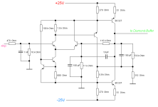
Since I'm not satisfied with Dr. Frankenstein's IPS-VAS either, I'm continuing to tinker with it.
This is followed by a quasi half diamond, with quite remarkable distortion of less than 0.004% (K2 only).
Balanced between the rails up to 44Vpp output voltage with Rload=10kOhm.
The circuit does not oscillate in the simulator, but as expected, the desired frequency response compensation is not possible. Nevertheless, this strange VAS works.
I used the evil C types as BJTs.
Attachments
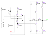
If I allow myself five more transistors, making a total of twelve (including the obligatory BC337 & BC327 of the original), then tomorrow or the day after tomorrow Tim will make a leap in his evolution that is quite something: the full diamond VAS! The internal single-ended operational amplifier becomes a balanced push-pull amplifier.
This thread is completely crazy .
.
This thread is completely crazy
.@wahab,
you asked for a fully symmetrical IP-VA stage, well - here it is.
Of course, we have to pay special attention to the power dissipation of Q1 & Q2 and the core must not get too warm, we know all that.
From your and Bernard's suggestions so far, which shapes all correspond in a broad sense to the Diamond sticker, I derive the designation Super-Diamond for the schematic in the file attachment. This basic circuit is therefore a Super-Diamond or nothing more than a discrete op-amp. With a very well known trick!
kindly regards,
HBt.
Psst.
THD_1k is < 0,005%
Attachments
Somehow they were really lucky, I can't get the original or even modified 1st stage to behave in a reasonable, constant way in the simulator - sometimes it goes /pass through, sometimes not.(...) The authors may have used a regulated supply and did not notice the ripple sensitivity. They were lucky that the amplifier worked.
But there is one point that I would like to comment on belatedly:
This is fundamentally the case and applies to every amplifier design, absolutely every design!The measured distortion is entirely consistent with the amount of negative feedback used.
Ed
Even though I probably know exactly what you mean, it doesn't have to be bad.
HBt.
Seems we are all victims of our unlimited cleverness
Hello Nico,
yes - that's us, without exception.
Greetings,
HBt.
Small correction; it should read 68.96mS for the C class. A six instead of a seven. Sorry for the typoWe are only interested in r_ce at the operating point, but also in S or gm, i.e. the slope ... 74.1mS applies to all members of class A (73.33mS for B; 78.96mS for C) ... all practically independent of the value V_ce_max of the individual.
.You /we could always realize the IP-VA stage with an operational amplifier (of your /our choice) or even couple the complete power amplifier to an IC, as the famous German “IGEL” from SAC (Axel Schäfer & Walter Fuchs) did, for example.
Because small hybrid modules can be so incredibly helpful, I like discrete OP-Amp. Design !
One rather important aspect should never be lost sight of: the morphed version can be controlled rail to rail. This is dangerous and the 25Wrms at static 8Ohms required here also represent the safe end of the swing.
At the latest when the output exceeds 30Wrms, some form of protective circuit (active or passive) must intervene.
If this point is ignored, it will lead to oscillations and other unpleasant things.
HBt.
Fellow campaigners wanted!
The product of the loop gain and THD is a mediocre 2%. The open loop amplifier could have been more linear.This is fundamentally the case and applies to every amplifier design, absolutely every design!
Even though I probably know exactly what you mean, it doesn't have to be bad.
Ed
Paper and pencilThe product of the loop gain and THD is a mediocre 2%. The open loop amplifier could have been more linear.
Ed
Even if I don't want to take up the cudgels for the Stellema design, we can go into detail and discuss the snot.
I do my research by hand (handwritten without a computer):
OLG approx. 78dB
CLG approx. 26dB
This largely agrees with the text specification, my +4dB difference is quickly justified, among other things because I rounded and in the parts list it is not specified which classification / selection the BJTs follow, so I took an average from all possible cases.
Based on a benevolent THD_20k with 0.01%, I even estimate 4% for the OLG case.
If we were now to implement the inner amplifier more linearly (which, among other things, would only be possible by means of local negative feedback, no matter in what form it would be hidden), then we could easily achieve 1% or even a little less, but at the same time also significantly reduce the OLG (Ao).
We reduce the self-made disturbance X and the factor by which it will now occur proportionally in the output signal, or subtracted.
At the end of the day, the final result (black box) is almost the same, as a number. The interference spectrum, or the Fourier decomposition, certainly looks different.
Greetings,
HBt.
(I hope I have simplified everything properly and translated it halfway correctly into English).
@EdGr
Yes, the original circuit is very curious and it gets its quite considerable THD values from the global negative feedback, one might think - alone.
It is clear that the IP is both the differential point and the actual voltage amplifier - at the latest since Douglas S. insisted on this, we have internalized that a clear separation and tripartite division is the most rational approach. The attached second part is an afterburner and not really the VAS.
IP 52dB + VA 26dB -> 78dB
This is not good, but, in the end, we always have to look at the negative feedback case. And take the entire construct apart in terms of measurement technology. How the Black Box works internally should not affect us in the first instance, we don't have to care.
If you look at how the Stellema original works in detail, it briefly becomes interesting from a forensic point of view. If you want to trace the period coloring, then there is no way around it. In the end, you can draw well-founded conclusions, which is always preferable to speculation - and also leads to finding detailed solutions/improvements if you want to stick to the topology and philosophy.
May be better to morph it into a 25W Krill ( with a new name: the crab! ) ?I
May be better to morph it into a 25W Krill ( with a new name: the crab! ) ?I
Yes, but high global feedback poses a greater engineering challenge. Stellema solved it with two-pole compensation (at 16KHz and 54KHz). That is impressive. I will stick with one-pole compensation (>20KHz) and a more linear open-loop.How the Black Box works internally should not affect us in the first instance, we don't have to care.
Ed
Thanks Ed
for the /this indirect reminder (of this topic).
#
I'll use the example of the youth competitions again, Discipline Fast breathing ability :
1st place
Class A with 6327 breaths per second
2nd place
Class B with 4079 breaths per second
3rd place
Class C with 2573 breaths per second
The absolute numerical values are insignificant, but the results of the class comparison clearly speak in favor of the members of class A as for the difference point IP (LTP) - firststage.
Wahab's observation
that a BC546-A should be used most sensibly at this point is technically absolutely correct. Or a 2SC2240-GR. The T.I.M. doctrine says the opposite -> use the C-type.
HBt.
Last edited:
- Home
- Amplifiers
- Solid State
- high performance 25W PowerAmp