I get a pretty noticeable click from the speaker relays engaging on my speakers. When I initially tested these amp modules they were long settled to a couple millivolt DC offset before the relay engaged. Solid state relays are likely the only cure for this. That's probably the next evolution I'm going to look into for the board.
I get a pretty noticeable click from the speaker relays engaging on my speakers. When I initially tested these amp modules they were long settled to a couple millivolt DC offset before the relay engaged. Solid state relays are likely the only cure for this. That's probably the next evolution I'm going to look into for the board.
Jeff, do you mean mechanical click from the relays? Or "electric" one from the speakers? My build of CFA-CFPx2 settles to couple of millivolts DC in about a second.
Jeff, do you mean mechanical click from the relays? Or "electric" one from the speakers? My build of CFA-CFPx2 settles to couple of millivolts DC in about a second.
I mean a click through the speakers. On the bench I measured a couple millivolts long before the relays cut in. These speakers are very sensitive.
21 st century ?
Where are the Mosfet relays ?
Cheers ,
Rens
A very good question, Rens
") (although you're not the first asking it )...
(although you're not the first asking it )...A couple of big enough gold-plated contacts don't add any noticeable distortion - I tested it, I measured it - I know it.
But, somehow - I'm an ancient dinosaur
- I never tried the MOSFET relays. However, I'd like to. So, this is the next thing to try and measure I mean a click through the speakers. On the bench I measured a couple millivolts long before the relays cut in. These speakers are very sensitive.
With my speakers couple of millivolts means absolute silence
Its probably just as easy to design a standalone board for for fan controls. Temp sensors connected to the analogue inputs would likely be more desirable. This board is pretty compacted. There's no way to get any more outputs to a connector without a major overhaul. I've managed to add two buffered outputs but I think that's about all I can squeeze and at that it will be sharing one 12V output for all the relays.
I agree - fan control is a cool idea, but in this case it's better to have analog reading from the sensors. At the currrent board design it's possible to use an unused channel to switch the fan on and off according to certain conditions, otherwise it requires pretty much of a redesign...
A very good question, Rens
A couple of big enough gold-plated contacts don't add any noticeable distortion - I tested it, I measured it - I know it.
But, somehow - I'm an ancient dinosaur
I've been looking at some of Elliot's designs for Mosfet relays. They don't look too terrible to work with. I've never even considered SS relays in the past because of resistance when closed and off state never really being off but these issues seem to have resolved long ago.
I misread his circuit. He's using mechanical relays for the speakers.
As I remember, he used both in parallel
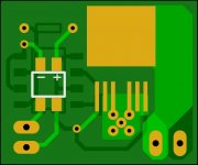
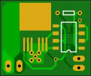
I've layed out a relay module to try based on Esperado's design. I omitted the Zeners across the output though. It's designed to stand upright in place of the Omron speaker relays.
Jeff, can you please drop the schematic for this board here.
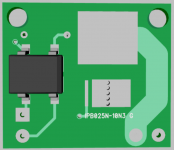
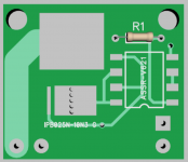
Now I just need to figure out how much copper is required to heat sink these things. The data sheet recommends 6 square cm but these shouldn't be anywhere near full output and hopefully aren't dropping any voltage so they shouldn't create much heat.
Attachments
- Home
- Amplifiers
- Solid State
- How to build a 21st century protection board