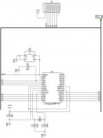
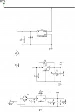
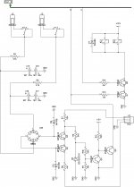
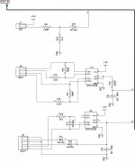
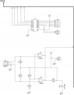
Schematic - version 3.3
Jeff has got issues with attachments - trying to attach from my account.
Split in 5 pages.
Cheers,
Valery
Jeff has got issues with attachments - trying to attach from my account.
Split in 5 pages.
Cheers,
Valery
Attachments
Jeff has got issues with attachments - trying to attach from my account.
Split in 5 pages.
Cheers,
Valery
Thanks
I added a couple extra outputs for future use as well. I didn't connect any of the analogue inputs though.
I'm more interested in this than the amps themselves.

You don't know the massive "22 century" leap you would make with the thermal/
overload monitored by using the analog. Rails ... too .
Here , you could script the "trip" points .... allowing for individual amp customizations.
The Solar power people not only use these analog inputs , but tie a SD card
to the ATmega to log long term analog fluctuations (with time stamp).
OS
Yes, using analog inputs for monitoring / measuring certain parameters, will be the next "leap". Built-in ADC allows doing it quickly and afficiently, enhancilg capabilities to infinity Imagination is the limit
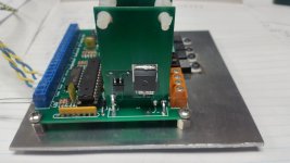
Thanks to Jeff for " tearing Arduino to pieces", so now we can use ATMega chip separately, making the board smaller and cheaper
P.S. I have also recently developed a solution, utilizing 74HC595N shift registers, allowing increasing the number of digital outputs to as many as required (8 additional outs per register).
Cheers,
Valery
Imagination is the limit Thanks to Jeff for " tearing Arduino to pieces", so now we can use ATMega chip separately, making the board smaller and cheaper
P.S. I have also recently developed a solution, utilizing 74HC595N shift registers, allowing increasing the number of digital outputs to as many as required (8 additional outs per register).
Cheers,
Valery
I thought about it as well. As far as the firmware is reasonably simple, it's ok to have it doing everything. But if we go for some relatively continuous analog tracking / processing, it's a good idea to have one chip mostly for startup/shutdown main cycle, and the other one doing all the rest continuous stuff independently, allowing protection to do its job very fast. ATMega chips are cheap
Do you think it would be safe to use analogue inputs to measure output device current? It would save quite a bit of external circuitry but the optoisolators are nice insurance. I would like to see thermal sensing done by the Atmega chip. It makes adjustment of parameters much simpler.
I'm still kicking around the idea of datalogging. A Raspberry Pi might be a good option because of the ease of networking. I have no idea of coding requirements though. That's something I've never had the time to learn.
Ah, right - a good task for a separate board with network interface. Then, we can arrange a portal and collect the logs there. If something goes wrong, it will be easy to analyse the historical log and see the issues caused the problem
Do you think it would be safe to use analogue inputs to measure output device current? It would save quite a bit of external circuitry but the optoisolators are nice insurance. I would like to see thermal sensing done by the Atmega chip. It makes adjustment of parameters much simpler.
Yes, I think some simple, relatively linear opto-decoupling circuit will be more than enough. It can also perform some "integration" (RC), so that you measure not the raw audio signal, but somewhat averaged values.
For a very good linearity - yes, op-amps are required. But for our purpose - some simpler circuits may be tried...
A good example of a linear device - HCNR200 and HCNR201 (High-Linearity Analog Optocouplers). In the worst case, LM393 may be used for "normalizing" the receiving side of it (2 op-amps per chip).
A good example of a linear device - HCNR200 and HCNR201 (High-Linearity Analog Optocouplers). In the worst case, LM393 may be used for "normalizing" the receiving side of it (2 op-amps per chip).
Why not just monitor the power supply directly to detect an overload condition ?
OS
That's another option. It could become a little more involved with the supply being shared with multiple channels. Positive rails and negative rails would likely need to be monitored separately. Emitter resistors are a convenient source for sensing with no added hardware to the amplifier other than two wire connections.
Hi Andrew, in fact, overload and short-circuit protection for the amp is already implemented in existing design. We are now thinking about monitoring the rails and some other parameters in time with appropriate logging
Jeff, the opto-couplers are linear enough, so even if we use op-amps for "normalization", it will only be required on receiving side. I mean - no isolated PSU required in any case.
Cheers,
Valery
Jeff, the opto-couplers are linear enough, so even if we use op-amps for "normalization", it will only be required on receiving side. I mean - no isolated PSU required in any case.
Cheers,
Valery
So far the Mosfet relays look good. I need to crank some high current through them yet to check resistance. My Fluke 88 says Zero on low resistance setting with no load. Hopefully they run cool enough that I can lop the top off the boards.
Attachments
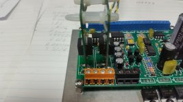
So far the Mosfet relays look good. I need to crank some high current through them yet to check resistance. My Fluke 88 says Zero on low resistance setting with no load. Hopefully they run cool enough that I can lop the top off the boards.
They look very cool! Such a tall PCB for them - is the idea to allow some heat dissipation?
- Home
- Amplifiers
- Solid State
- How to build a 21st century protection board