They look very cool! Such a tall PCB for them - is the idea to allow some heat dissipation?
Yes. The top 22mm is just heat sink.
So far the Mosfet relays look good. I need to crank some high current through them yet to check resistance. My Fluke 88 says Zero on low resistance setting with no load. Hopefully they run cool enough that I can lop the top off the boards.
So that is the FET relay. !
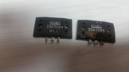
 What devices are you using for the mosfet ?
Typical 34 milliohm mosfet Rdson at 10A is .3v drop and only >3W dissipation.
Should be as cold as a output emitter resistor.
OS
I used Infineon IPB025N10N3 G fets. I think I'm going to keep evolving this project. If these run cool they will be integrated into the next board design.
They should stay cool as a cucumber, Rds-on is a maximum of 2.5mΩ for the device. Dissipation should stay under 1W for just about any audio application.
The Mosfet relays seem to be working well. I haven't been able to measure any voltage drop across them in use and there's no heat generated either. I need to build up a couple more samples before I do any torture testing on them. No short circuit or heavy DC testing yet.
Cool ! Jeff ....
I'm building these now. SMD is harder , no shaking hands-very fine tip and
I'm barely able to do a good job.
I have a version 8 script for the ATmega that I have perfected on the old setup.
Having a problem getting my PC's to communicate with the UNO.
OS
Cool ! Jeff ....
I'm building these now. SMD is harder , no shaking hands-very fine tip and
I'm barely able to do a good job.
I have a version 8 script for the ATmega that I have perfected on the old setup.
Having a problem getting my PC's to communicate with the UNO.
OS
I figured out an easy way to assemble the relay. Install the driver IC first so you can solder both sides. Next poke resistor lead trimmings through the vias for the Mosfets and lightly solder them in place. That helps carry current from one side of the board to the other, and also aligns the mosfet for you. Much easier than trying to line it up. I use a 75 amp alligator clip from a battery charger to hold everything in place and align everything with tweezers.
The Uno is usually the easiest Arduino to connect. You need to select Uno in tools and change your com port though. The hardest part is prying the Atmega out of the socket the first time. I think they solder it in but it will pry out.
I have recently got Uno exactly for this purpose
The uno has the big wide "breakout" pin-rows to attach to a breadboard.
Big "fat" printer type USB connect (looks very durable). All the breakouts
are clearly marked.
It looks like the perfect setup for development of the "A0 -A5 + Aref"
(analog section).
OS
The uno has the big wide "breakout" pin-rows to attach to a breadboard.
Big "fat" printer type USB connect (looks very durable). All the breakouts
are clearly marked.
It looks like the perfect setup for development of the "A0 -A5 + Aref"
(analog section).
OS
I give kids Uno kits with the breadboard and components if they want to learn programming. It's much easier to work with and if they fry an in/out the Atmega is easier to change than the SMD versions.
People have posted tons of cool projects on Newark's/Element 14 Forums. They go way more advanced that the Arduino playground there.
I'm just a "big kid" - ask the wife ...
OS
Same here, the wife is long gone.
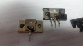
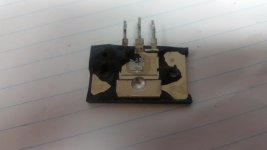
I managed to blow up a solid state relay. It blew open like I was hoping. I still need to disassemble the relay from the protection board to see if the actual mosfet failed or if it was the clamping diode. It took a Slewmaster with 63V rails in full oscillation into 4 ohms to the damage. The MT200s let out a pretty good bang at the same time.
Attachments
I managed to blow up a solid state relay. It blew open like I was hoping. I still need to disassemble the relay from the protection board to see if the actual mosfet failed or if it was the clamping diode. It took a Slewmaster with 63V rails in full oscillation into 4 ohms to the damage. The MT200s let out a pretty good bang at the same time.
WOW ! break one open so we can see ...
Oscillation might of caused thermal derating (SOA dropped).
Should I hold off and just use my board for AC control for now ?
OS
This was an intentional failure. I assembled a two pair board and set it up to oscillate just to see what would happen to the relay. It was actually a pretty tough go to fry it. I think normally the current limit and temperature limit would have shut the amp down long before this point. I had Thimos' glowing Zobel resistor happening too.
Try just shorting out an amp playing music in normal operation.
PS - I guess the worst case scenario of a oscillating amp is a valid test.
I doubt the SS relay projects from other members ever got this test.
I have not seen it.
Show some pictures ...
OS
If there's any chance of danger I test a prototype to death in my office. Stainless benchtop, fire rated drywall and a fire extinguisher under the bench.
These MT200s look like beefy TO3-Ps bonded in a bigger case. The case rupture happened right over the emitter leg connection in both. I'll dissect the mosfet when I get it apart.
Attachments
- Home
- Amplifiers
- Solid State
- How to build a 21st century protection board