EDITED:
The amp I used for testing uses discrete transistors. I don't remember anymore but I think it's bipolar. It is a clone of the Burmester 956.
To output from the Scarlett, I use the TRS output 1 on the back with a TS->RCA cable from Thomann.
To input in the Scarlett, I use the front TRS input 1 with a TRS-RCA custom cable (with the resistors in the TRS plug).
Input/output 2 is connected with a XLR-XLR cable on the back.
This is a Scarlett 2i2 4th gen. I used to have an old Tascam but it died and I bought myself a Scarlett.
Last edited:
I recommend the offical REW forum:
https://www.avnirvana.com/forums/official-rew-room-eq-wizard-support-forum.10/
https://www.avnirvana.com/forums/official-rew-room-eq-wizard-support-forum.10/
What aspect of the two measurements is not acceptable to you? The 40Hz peak, the THD+N, ...?The problem is that depending on the type of attenuator, I don't get the same result at all.
Did a loopback test of each attenuator show exactly the same frequency and distortion and noise floor response?
Are you using the same 'gnd' location in your amp for connection of the input and output signals going to your setup, or is there a ground link between those connections running through the amp ? If your soundcard doesn't connect to the same gnd point, then any link between those two connection points can cause a ground loop if there is extraneous signal across that link.
Thank you for all your suggestions. I will do different tests and I will tell you.
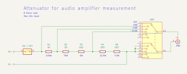
I haven't found anything to do with 900R and 9K except to use a ton of resistors in parallel and series which will not fit in a TS jack. I would order some on occasion. For now, I'll stick with what I have.
I also drew this diagram of a direct attenuator with the load. I have most of the resistors except 2 that I would need to order.
What did you think of this type of attenuator?
Stef.
Attachments
Hello Jan,
I'm just trying to find the attenuator that gives the best results. So I'm thinking about different possible techniques knowing that some will surely be bad and/or more complex.
I redid the measurements with the two attenuators. I made a second identical cable for the 1K-100R one because before these resistors were connected to the power resistors in the box.
So I now have two almost identical cables only the version of the attenuator differs.
I tested them in loopback directly in the Scarlett. I exit through port 1 OUT on the back in TS and I enter through port 1 IN on the front in TS.
They give practically the same result. There is just a small difference in level due to the imprecision of the attenuations.
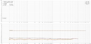
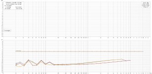
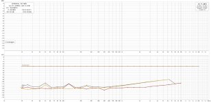
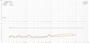
Then, I did the same measurements but crossing the amp. Now that the 1K/100R resistors are in the TS socket, the result is better but the low impedance cable seems much more sensitive to 50Hz disturbance than the high impedance one.
I'll give you the 4 measurements.
Stef.
I'm just trying to find the attenuator that gives the best results. So I'm thinking about different possible techniques knowing that some will surely be bad and/or more complex.
I redid the measurements with the two attenuators. I made a second identical cable for the 1K-100R one because before these resistors were connected to the power resistors in the box.
So I now have two almost identical cables only the version of the attenuator differs.
I tested them in loopback directly in the Scarlett. I exit through port 1 OUT on the back in TS and I enter through port 1 IN on the front in TS.
They give practically the same result. There is just a small difference in level due to the imprecision of the attenuations.
Then, I did the same measurements but crossing the amp. Now that the 1K/100R resistors are in the TS socket, the result is better but the low impedance cable seems much more sensitive to 50Hz disturbance than the high impedance one.
I'll give you the 4 measurements.
Stef.
Attachments

Except for the hum they are basically identical.
In my view you are chasing the wrong ghosts.
What you need to concentrate on is a good wiring setup, good cables, avoiding ground loops, single point grounding etc.
Read the REW user guide and application guides and follow those precisely.
At this point your are fiddling with multiple things, the cabling, the attenuators and Ohm knows what. A recipe for wasting everybodies time.
Jan
Yes, I use a .cal file for the Scarlett.
It's not that easy to take measurements and I'm trying to learn.
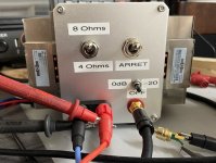
I'll show you a photo of my test box. It's done with 2 servers heatsinks that I recovered, 2 4R/100W resistors in series and a box for €5. Originally, I put the attenuator in the box but for the test, it now bypassed.
I'm going to read the literature on the subject to see where I'm making mistakes. The cables may not be well made. I was also wondering if I should connect the box to the GND of the RCA.
Stef.
It's not that easy to take measurements and I'm trying to learn.
I'll show you a photo of my test box. It's done with 2 servers heatsinks that I recovered, 2 4R/100W resistors in series and a box for €5. Originally, I put the attenuator in the box but for the test, it now bypassed.
I'm going to read the literature on the subject to see where I'm making mistakes. The cables may not be well made. I was also wondering if I should connect the box to the GND of the RCA.
Stef.
Attachments
Generally you should treat the RCA ground as one of a pair of signal wires (which it really is).
So take your cabling from one connetor to another BOTH leads.
Ideally, isolate all RCAs from the chassis and/or box metal and connect the box/chassis to the RCA ground at one point only, generally the input RCA ground works best.
If you mount the RCA on the box, there is no need to ground it also somewhere else, actually that may screw things up with ground loops.
Edit: that croc clamp on the RCA is not the way to do it. Use screened cable. All cabling is part of the circuit!
I see people (not you) using crappy cabling to connect a $200 supercap and I weep ...
Trust me, in sensitive measurements like this, every electron counts!
Jan
Last edited:
The GND of the RCA mounted on the measuring box is not connected to the box (nor the neg coming from the HP as well).
Where can I find an example of the ideal wiring for these measurements for my two TS-RCA cables?
Knowing that I have TS and TRS male sockets, 2-conductors cable (for asymmetrical) or 3-conductors (for balanced) in stock. I am ready to redo the cables if necessary.")
Stef.
ps: the crocodile clamp that we see on the picture is a part of the oscilloscope probe which is not currently used for these tests. I was also looking for an adapter for the end of the probe (when you remove the plastic part with the hook) to be able to easily plug it into an RCA or another type of connector. Or, I can make something with a piece of rigid wire like when I measure power supplies for better GND connexion.
Where can I find an example of the ideal wiring for these measurements for my two TS-RCA cables?
Knowing that I have TS and TRS male sockets, 2-conductors cable (for asymmetrical) or 3-conductors (for balanced) in stock. I am ready to redo the cables if necessary.
Stef.
ps: the crocodile clamp that we see on the picture is a part of the oscilloscope probe which is not currently used for these tests. I was also looking for an adapter for the end of the probe (when you remove the plastic part with the hook) to be able to easily plug it into an RCA or another type of connector. Or, I can make something with a piece of rigid wire like when I measure power supplies for better GND connexion.
Hello,
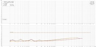
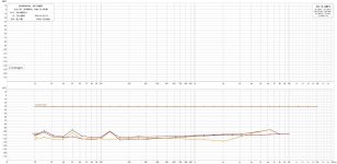
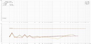
Just to let you know that I did a few more tests. I compared the 10:1 10K/1K1 attenuator. A version "in the cable" and the second "in the box" (I replaced the original 1K/110R attenuator).
The winner is the version in the box.
I tried with 2 amps of which there is just one board powered on the workbench.
Does these measures seem consistent to you?
In any case, thank you for your advice.
Stef.
Attachments
- Home
- Design & Build
- Software Tools
- How to - Distortion Measurements with REW