They are the measures of the 2 cables in loopback config as explained in the 1808 post.
Attenuator cable in the output and input of port 1 of the Scarlett. No amplifier in the loop.
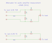
I made a new 10K/1K1 attenuator TRS-RCA cable like RANE No. 18. I'll try it tomorrow. Currently, I use a TS-RCA attenuator cable as No. 19.
Stef.
Attenuator cable in the output and input of port 1 of the Scarlett. No amplifier in the loop.
I made a new 10K/1K1 attenuator TRS-RCA cable like RANE No. 18. I'll try it tomorrow. Currently, I use a TS-RCA attenuator cable as No. 19.
Stef.
Hello Jan,
I tried a new cable to try to solve the hum problem.
I tried the new attenuator cable based on No 18 RAN cable (GND not connected and attenuator resistors between +/-).
The stepped SIN with REW generator is better. Hum is gone. See screen shot.
BUT
If in place of internal REW generator, I use the external 1KHz generator, signal is not good. See second screen shot.
If I replace the new attenuator cable with the old one using RAN No 19 wiring (GND connected), signal is ok as previously posted.
I have to try the cable given in the example included in the post and I think I would have tried all the cable variations.
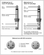
If this is not understandable, I can draw the wiring of the various cables that I made and post them here.
Stef.
I tried a new cable to try to solve the hum problem.
I tried the new attenuator cable based on No 18 RAN cable (GND not connected and attenuator resistors between +/-).
The stepped SIN with REW generator is better. Hum is gone. See screen shot.
BUT
If in place of internal REW generator, I use the external 1KHz generator, signal is not good. See second screen shot.
If I replace the new attenuator cable with the old one using RAN No 19 wiring (GND connected), signal is ok as previously posted.
I have to try the cable given in the example included in the post and I think I would have tried all the cable variations.
If this is not understandable, I can draw the wiring of the various cables that I made and post them here.
Stef.
Attachments
Post crossed.
The end of the test.
With a cable as in the EMU drawing (I call it cable T), the stepped sin is better than with the cable No 18.
The external signal with victor oscillator is better than with the cable No 18 BUT the h2/H3 do not have the same level as with cable TS (No 19).
First screen shot: cable T
Second screen shot: cable T
Third screen shot: cable TS
So I can't find a cable that works in all situations.
The T-cable (as EMU drawing) is best for working with REW using the REW generator.
The basic TS cable gives the best result with the external Victor oscillator.
Attachments

Yes, it is progressing little by little. ")
Do you have an explanation why the harmonics of the Victor oscillator move so much in level from one measure to another depending of the cables?
Perhaps the -20dB attenuator at the Victor's oscillator output is not optimized.
It really bothers me that the H2 moves so much from one measurement to the next so it's really hard to know where the truth is. It also moves if I touch the entry level on the Scarlett. The h2 level being an important parameter when optimizing components of an amplifier.
I need to improve the T-cable because for the moment, it is like in the photo and it experiences electrical disturbances at times. From one measurement to another the level 50Hz, 100Hz at times rises suddenly.
Stef.
Attachments
Last edited:
It could be that you have too little attenuation in the attenuator and that the soundcars level is very much turned down.It really bothers me that the H2 moves so much from one measurement to the next so it's really hard to know where the truth is. It also moves if I touch the entry level on the Scarlett. The h2 level being an important parameter when optimizing components of an amplifier.
Small vibrations and mechanical noise can change level when measuring.
Ideally the sound card level should be close to max and the attenuation before that.
How far is the volume control of the sound card turned?
That cable looks OK.
Jan
Victor's oscillator is in charge. I have to wait until the battery is charged again to do further tests.
My boxed oscillator is on this post: https://www.diyaudio.com/community/...urements-with-rew.338511/page-86#post-7484364
The curve I put at the time is really bad. I didn't master REW at all and I had the old Tascam at the time. Now the entire installation is on battery (including the NUC PC and its screen) and I have a Hifime High-Speed USB Isolator v2 USB cable to complete the insulation.
I don't remember what resistance I put in the oscillator for the -20dB attenuator. This may also be important.
What would be the best values for -6db and -20dB for Victor's oscillator and amp inputs around 22K or 47K?
IIRC, Viktor's oscillator cannot turned down to less than 1.5V or so.
Which input value to the amp do you use?
It would at any rate be smart to look at the waveform on the REW scope screen to make sure it's a nice sine.
Edit: thye Viktor has 600 ohms Rout, so you can put an attenuator/potmeter there of say 5k.
\
Jan
Which input value to the amp do you use?
It would at any rate be smart to look at the waveform on the REW scope screen to make sure it's a nice sine.
Edit: thye Viktor has 600 ohms Rout, so you can put an attenuator/potmeter there of say 5k.
\
Jan
I'll have to take it apart to see what I did.
In the meantime, I played with REW's internal oscillator and tried to understand the problem with h2 going up and down depending on the settings.
I didn't understand at the moment. So I'll give you the method used to see where I'm making a mistake.
I use the -20dB T cable from the 8R load to the Scarlett.
I set the port 1 input knob to 0dB (at minimum).
I set the port 1 output knob to 0dB (at minimum).
I position the REW generator at -12dB.
I turn on the amp and with the REW generator and the REW oscilloscope, I raise the volume of the output port to the clip (on this amp model, I can't do it but I'm around 25V/28V). The output port volume is turned up.
I cut the REW generator and put it at -30dB.
I start the generator and look at what appears on the multimeter. I enter the value into the REW generator, i.e. 2.77V.
Then I set port two so that it is also at -30dB (it does not go below 35dB) like the other signals.
I check that everything is correct. I send 3V, I have 3 volts on the multimeter. I send 10V, same thing.
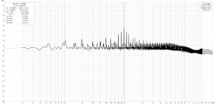
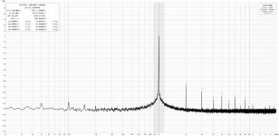
Then I go to RTA and send 2.83V with the generator (around -30dB). I have the correct voltage on the multimeter. I display the spectrum. This is the first screenshot.
I then turn the Port 1 input knob to go from 0dB to 12db. I'm still in the green zone on the Scarlett software. This is the second screenshot. Its takes intermediate values, we see the h2 rise little by little.
I don't understand why the h2 goes up like that. If we look at the distortion of H2 at the top left, it has increased enormously.
There must be something I didn't understand or another bad setting with the hardware.
Stef.
In the meantime, I played with REW's internal oscillator and tried to understand the problem with h2 going up and down depending on the settings.
I didn't understand at the moment. So I'll give you the method used to see where I'm making a mistake.
I use the -20dB T cable from the 8R load to the Scarlett.
I set the port 1 input knob to 0dB (at minimum).
I set the port 1 output knob to 0dB (at minimum).
I position the REW generator at -12dB.
I turn on the amp and with the REW generator and the REW oscilloscope, I raise the volume of the output port to the clip (on this amp model, I can't do it but I'm around 25V/28V). The output port volume is turned up.
I cut the REW generator and put it at -30dB.
I start the generator and look at what appears on the multimeter. I enter the value into the REW generator, i.e. 2.77V.
Then I set port two so that it is also at -30dB (it does not go below 35dB) like the other signals.
I check that everything is correct. I send 3V, I have 3 volts on the multimeter. I send 10V, same thing.
Then I go to RTA and send 2.83V with the generator (around -30dB). I have the correct voltage on the multimeter. I display the spectrum. This is the first screenshot.
I then turn the Port 1 input knob to go from 0dB to 12db. I'm still in the green zone on the Scarlett software. This is the second screenshot. Its takes intermediate values, we see the h2 rise little by little.
I don't understand why the h2 goes up like that. If we look at the distortion of H2 at the top left, it has increased enormously.
There must be something I didn't understand or another bad setting with the hardware.
Stef.
Attachments
If you turn up the volume to the amp, it is quite normal that distortion rises.
If you continue, you eventually hit clippinmg and then distortion goes to the roof.
So it looks that what you see is to be expected and quite normal.
Another tip: set the display of the fundamental in REW to 0dB in both cases. That makes it easy to compare the two situations.
The way it is now you need to do some mental calculations to compare the two situations.
BTW I don't understand the caption on both graphs. Both say 'Burmester_1W' but one says '-12dB'.
Are the levels coming out of the amp the same or different?
Jan
Hello Jan,
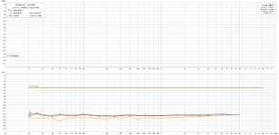
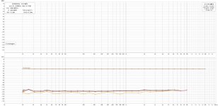
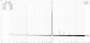
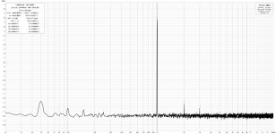
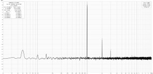
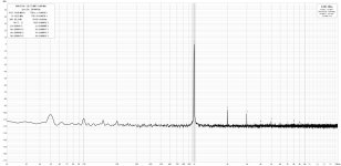
I made you 2 new measurements centered on the Victor oscillator and the two versions of the cables.
The amp outputs 2.83 Vrms via the Victor oscillator at amp input.
I set the REW RTA to 0dBu. The Scarlett's INPUT port 1 potentiometer is at 0dB.
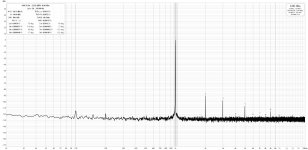
First graphic: RCA-TS 10:1 cable
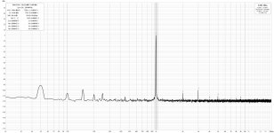
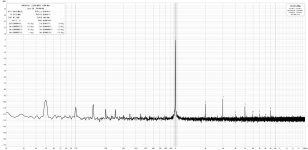
Second graph: RCA-TRS cable (T-Cable) 10:1
The harmonic levels are not the same.
Stef.
I made you 2 new measurements centered on the Victor oscillator and the two versions of the cables.
The amp outputs 2.83 Vrms via the Victor oscillator at amp input.
I set the REW RTA to 0dBu. The Scarlett's INPUT port 1 potentiometer is at 0dB.
First graphic: RCA-TS 10:1 cable
Second graph: RCA-TRS cable (T-Cable) 10:1
The harmonic levels are not the same.
Stef.
Attachments
I see, the first is better, also lower hum. I can think of one issue:
By connecting the amp output, which is connected to gnd on one side, via a balanced attenuator to the Scarlet, you introduce part of the amplifier ground into the signal to the Scarlet. Is there a ground connection between the Scarlet to the amp?
Anyway you have made a lot of progress, your measurements look good.
Jan
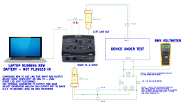
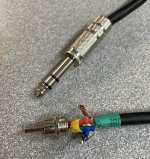
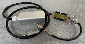
Here are the 2 cables.
The TS cable is a commercial cable (Sommer Cable Basic HBA-62C2 1.5m). The attenuator is in the load box.
When I switch from the TS cable to the TSR cable, I set the load box to 0db (direct connection to the 8R load without the 2 resistors).
With the Victor's oscillator, the TS cable give better measurement. It's the opposite if I use the REW oscillator, the TSR cable gives better results but always with the harmonics moving.
Stef.
EDIT: the 8R load is done with 2 4R Caddock resistors https://www.mouser.fr/ProductDetail/684-MP9100-4.
Attachments
Last edited:
Good morning,
To complete the measurements, I have the same tests with the Victor oscillator and the two cables but with the amplifier at 5Vrms and 10Vrms output.
The measurement type is written as file name.
Stef.
To complete the measurements, I have the same tests with the Victor oscillator and the two cables but with the amplifier at 5Vrms and 10Vrms output.
The measurement type is written as file name.
Stef.
Attachments

- Home
- Design & Build
- Software Tools
- How to - Distortion Measurements with REW