Really dont want to Hijack this great thread started by respected DIY Member Audiodesign.
Just my last quick answer for Pauldune:
Capacitors can only to smooth 100Hz DC pulsating current but Not to `short `any DC pulsating current komponents.Try a litle scope probe,You can see thats always remain some 100Hz pulsating rest across capacitors whatever which capacitors value is incorporated.
If capacitors realy `shorts` any AC component on the top of DC current, on the scope screen will be perfect Flat line but usualy is Not.
Best Regards
And my really last one to you, otherwise we should start a new thread for our own.. sincere apologies to threadstarter!
But...
The effect you see is because of the dynamic impedance of the cap; its not zero. It behaves as a normal resistor and is for example 5 or 10 ohms at 100Hz.
Because there is current flowing through that resistor, it drops voltage, thats what your measuring. if it was a perfect capacitor, you would measure nothing!
greetings, Paul
")
Michael,
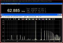
I have tested your hybrid circuit in my 2A3 PSE cheap amp. but the sound was orrible.
New 2A3
You tested my circuit? LOL
I assume you mean your "RJM Kimmel modified"
Looks similat to my circuit; oh except for cathode bypass cap on the D3a
 oh and the interstage coupling cap. Oh and the MOSFET, did you know the selection of MOSFET and component values is important to getting good sound? You don't show any of this How do I know what you built? Did you try a cascode or any circuit tuning?
I doubt you understand the intent of my circuit, which is to drive a power grid into A2 operation with a minimum of distortion. My amps sounded and measured very nice, and the measurements are up for all to see on this board. Your circuit with coupling caps etc. will suffer from blocking distortion and OP shift with signal. No wonder it sounds "orrible"!
Looking at your measurement (attached), what's up with that? I never saw anything that ugly on my amp.
Tell you what, in the future I'll stay the heck out of your threads and you stop claiming to be building "my" circuits when you're not. OK? OK.
Jeez, I was trying to make a case for your circlotron circuit having great PSRR due to the high dynamic resistance of the MOSFETS.
Ciao,
Michael
Attachments
Last edited:
Let me apologize for responding in kind...
What I meant to say was more like this:
Hi Andrea,
I'm sorry you didn't have success at duplicating the results of one of my circuit ideas, in particular the "Meteor" A2 amplifier. In reviewing your excellent documentation of the Cheap 2A3 project, I would like to make some suggestions.
First, the circuit won't perform as designed using a D3a and RC self-bias. The driver tube does carry some of the load in driving the grid, (more on this later) amd the bias needs to be "stiff", hence my use of a diode-connected MOSFET. The dynamic resiscance curve of this device also impacts the sonic signature, so it must be selected along with the tube depending on the power grid load characteristics. For the D3a I would recommend starting with a MPSA12 Darlington NPN transistor in the diode connection.
Next, the circuit will happily provide a couple hundred mA of grid current, so in my experience using such a low impedance driver with a coupling cap in a low power SE triode amp is asking for blocking behavior. The circuit was designed to be directly coupled to the power grid for blocking-free smooth transition into A2 operation.
Then, the active load device selection and operating parameters are important. It's important to understand that the MOSFET and tube work in a complementary drive arrangement and some current is passed back and forth due to the finite gm of the MOSFET. This is more important of course with a super-high gm tube like the D3a. What's important here is to understand the operating region of the MOSFET into the load and select one for a good fit with the tube, all depending on the selection of the resistor value which drops voltage as the load current increases, providing drive voltage for the MOSFET. Increasing the value of this resistor puts more of the dynamic load current through the MOSFET, and of course exposes more of the MOSFET characteristic in the output to the power grid load. I would start with a DN2540 and maybe add the IXTP01N100D as top device in a cascode. Then I would tune the resistor value by FFT and by ear together.
Looking at yout FFT measurement, I would suspect something is going wrong due to either the coupling /cathode bypass caps maybe due to more gain than the R load version... or maybe some gross error in device suitability (what MOSFET did you use?) or op point. e.g. you need enough voltage headroom on the MOSFET.
So had I known you were trying to duplicate my results I could have helped resolve some of these misunderstandings up front. I think using the Meteor approach with a D3a => 2A3 and mild A2 operation has great promise with some 2A3 types, but the important aspects need to be considered in the implementation.
My Meteor amp actually sounded and measured quite nice, with a harmonic signature mainly consisting of f2 and f3 and had very little hum or noise; not 'orrible at all, thank you!
By the way, in posting my example circuit I was trying to make a point about your very cool and clever circlotron circuit, that the high dynamic resistance of the MOSFETS does a great job of isolating the power supply from the signal. My amp has 4V ripple on the driver +supply rail and no measurable ripple on the grid.
Peace,
Michael
Last edited:
After 3 different listen sections on the prototype with different friends I can confirm that this amplifier is superior to my 813/GM70 SE, Hybrid 2010, PP2010 and New Class D.
The propagation speed of sound is terrible and attracts and involves everyone who hears.
The level of details is extreme and never is present a listening fatigue.
It is very difficult return to ear any other amplifier after these listen tests.
I suggest it to any DIY in any version, with 5842 or 6C45, with CLR power supply or simple and with any type of mosfet suggested.
You can build it also with surplus components and the unique "big" cost will be the interstage transformers Lundahl LL1671.
I will continue to develop this project in this year and I am selling the other amplifiers.
This topoloy is better than that of the most commercial available amps, independend from the class of costs.
I have testet only such a output stage (source follower mode, <unity gain).
Despite the use of enhance mosfets (IRF240) instead audio mosfets the sound quality is such as those described by you with the disadvantage of a little to low acoustical power.
By the use of a high voltage gain line preamp like Convergent audio Technology SL1 Ultimate Mk 2 Preamplifier the obtain sound quality is completely satisfactory.
But I assume without tubes in the signal path of voltage gain stages I forces the quality enhancement additional cause no longer exist microfonic effects. This means, solid state voltage gain stage (VAS) is necessary. Most music lowers claim, that isn't possible without audible disadvantage. But with the right topology this actually must be possible - I think.
I prefer therefore the Larvadin/Lavardin VAS stage, describted about
http://peufeu.free.fr/audio/memory/memory-8-complete.html
If I have time, I will check out this.
Last edited:
Member
Joined 2009
Paid Member
After 3 different listen sections on the prototype with different friends I can confirm that this amplifier is superior to my 813/GM70 SE, Hybrid 2010, PP2010 and New Class D.
The propagation speed of sound is terrible and attracts and involves everyone who hears.
The level of details is extreme and never is present a listening fatigue.
It is very difficult return to ear any other amplifier after these listen tests.
I suggest it to any DIY in any version, with 5842 or 6C45, with CLR power supply or simple and with any type of mosfet suggested.
You can build it also with surplus components and the unique "big" cost will be the interstage transformers Lundahl LL1671.
I will continue to develop this project in this year and I am selling the other amplifiers.
That's great news, it's what this hobby is all about. Please keep us informed of changes in your thoughts about this amplifier and any changes to the design.
Really enjoy reading this great thread started by Audiodesign.
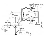
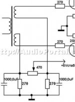
This Audiodesign A class Hybrid Circlotron power Amp design is on my `must do` DIY list for sure, since I have some old stash of original Hitachi 2sk135 device and few 6c45p tubes, and excelent sonics experience with pure tube OTL A class Circlotron based power Amps.
Have one Russian similar design Hybrid A class Cirlcotron from year 1995.
This Russian designer reported excelent sonics too for his Hybrid Circlotron power Amps simillar like Audiodesign was, but he reported that sonics performance was mostly limited with his `hand made` interstage transformer.
Hi used pentode tube 6P15P triode strapped for input/driver stage.
Best Regards for All
Attachments
Last edited:
Great news!After 3 different listen sections on the prototype with different friends I can confirm that this amplifier is superior to my 813/GM70 SE, Hybrid 2010, PP2010 and New Class D.
The propagation speed of sound is terrible and attracts and involves everyone who hears.
The level of details is extreme and never is present a listening fatigue.
It is very difficult return to ear any other amplifier after these listen tests.
I suggest it to any DIY in any version, with 5842 or 6C45, with CLR power supply or simple and with any type of mosfet suggested.
You can build it also with surplus components and the unique "big" cost will be the interstage transformers Lundahl LL1671.
I will continue to develop this project in this year and I am selling the other amplifiers.
PLEASE keep us updated!!
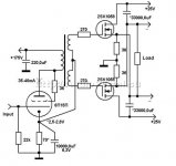
I see as large influence in the sound the cathode capacitor that I cannot eliminate but it can be considered an advantage because you can use it to modify the sound..
Why don't you eliminate that cathode capacitor with fixed bias?
The regulated Bias PSU section is too complicated for me.Yes, you can use a battery to bias the mosfet but why ?
Do you know how much current has to deliver the +3.5V Bias power supply?
Tyimo
URL Collection concerning the topic Totem-Pole/CSPP/Single-ended-related Stages
about
http://www.diyaudio.com/forums/soli...e-ended-related-solid-state-output-stage.html
you will find various URLs for more ideas.
about
http://www.diyaudio.com/forums/soli...e-ended-related-solid-state-output-stage.html
you will find various URLs for more ideas.
- Home
- Amplifiers
- Tubes / Valves
- Hybrid Circlotron Amplifier with only 3 components on the signal path