I dont think so
It s a mkt cap
For small size cap,you can go for pps cap ( panasonic for example)
You're right - I think its WIMA MKS 2, which is metallized polyester.
Anyway, I swapped it with a RIFA PHE 426 (polyprop). Any audible difference? ... don't think so!
This type of mod reminds me of when I bypassed the 100 uF electrolytic coupling caps (between DAC and buffer) in my Logitech Transporter. There was not difference at all.
I kinda like the sound of the ICEpower modules I've used. Strong bass, good dynamics and they sound very neutral to me. Some who have heard them accused them of a "soft" top end, but maybe that's just a lack of distortion?
I've only used the modules with built in power supply, so can't comment on the others.
I've only used the modules with built in power supply, so can't comment on the others.
I know the ICEpower modules very well, having build a lot of amps with them, and I have used them in my own system for a long time as well. Yes - the top end is a bit soft and lack details compared with "better" amps, but the difference is fairly small ...
Pano - what ICEpower modules do you use?
Pano - what ICEpower modules do you use?
quite some good discussion. here's a few thoughts of mine...
to the original Q from DJNUBZ: IMO, yes, class-D is at the "level" of F5. Now, I must admit to never hearing an F5, so this is general statement. I've heard many good class A amps. Including other Pass. (and good class A/B as well of course...)
I heard ICEpower sometime back, and was not impressed. They may have improved. Things are still changing all the time...
I've also listened a fair bit to Nuforce class-D amps. (with same speakers I have, but not in my home) The Nuforce were quite good, nothing obvious wrong. Though I think they are not as good as my amps )
)
I'm listening right now to my hypex UCD 400's. The full build cost was > $1K. But if I had to do over, I'd go for UCD180 and scale down the build a little. (I have speakers of decent efficiency now) The UCD 400's sound wonderful and have compared well to everything else I've listened to.
I'm using the "HG" model with the HxR regs. Power supply, as always is important. And I got lazy to build my own at the time though there are many great ways to go.
Using the UCD as an output stage (current buffer) is also a decent way to go. I'm planning to experiment with this soon, bypassing the input opamp and caps and using a different gain stage. Maybe tube based
I also have a tripath 41Hz board to build one of these days - wanted to hear how they sound... only so much time...
to the original Q from DJNUBZ: IMO, yes, class-D is at the "level" of F5. Now, I must admit to never hearing an F5, so this is general statement. I've heard many good class A amps. Including other Pass. (and good class A/B as well of course...)
I heard ICEpower sometime back, and was not impressed. They may have improved. Things are still changing all the time...
I've also listened a fair bit to Nuforce class-D amps. (with same speakers I have, but not in my home) The Nuforce were quite good, nothing obvious wrong. Though I think they are not as good as my amps
)I'm listening right now to my hypex UCD 400's. The full build cost was > $1K. But if I had to do over, I'd go for UCD180 and scale down the build a little. (I have speakers of decent efficiency now) The UCD 400's sound wonderful and have compared well to everything else I've listened to.
I'm using the "HG" model with the HxR regs. Power supply, as always is important. And I got lazy to build my own at the time though there are many great ways to go.
Using the UCD as an output stage (current buffer) is also a decent way to go. I'm planning to experiment with this soon, bypassing the input opamp and caps and using a different gain stage. Maybe tube based
I also have a tripath 41Hz board to build one of these days - wanted to hear how they sound... only so much time...
I think the gain of the opamp is around 14 dB or 5x -you can read it in the UCD technology paper on Hypex Electronics BV
Quote from the last section: "The similarity is more than passing. The UcD con op-amp buffer is a functional instrumentation amplifier with high-impedance inputs and with a CMRR which is improved by a factor equal to the gain of the first stage. The gain structure in a typical implementation is 5 for the input stage and 4.5 for the subsequent UcD. CMRR-wise it would have been better to have all the gain realised in the first stage, but a standard IC op amp wouldn’t cut it because of the voltage swing it would have to deliver."
If I´m going the UCD way I will definetely try that approach too. Any experiences out there on the audible effects of driving the UCD modulator directly by the preamp?
If I´m going the UCD way I will definetely try that approach too. Any experiences out there on the audible effects of driving the UCD modulator directly by the preamp?
Quite some DIY'ers experiment with non-IC front ends, wether it discrete SS or tube. I wound interstage transformers for tube stages for this application.
Important is to know that input impedance of the UCD modulator is rather low and also very different for each phase (when I am right one of the phases has 2k input impedance, the other phase 10k, but correct me if I am wrong); a low output impedance pre-stage is therefore required, which could be done by step-down interstage transformers and driver tubes with mu of 15 to 20.
Also by transformer coupling there is no need for "bad" electrolytic coupling capacitors
a.wayne,
Thanks for your elaborate description. As we probably all can agree on, there is no perfect technology and all have each their good and bad sides, which is why our different preferences makes this hobby so fun. According to the `live´ appeal your refer to in the class D implemantations you´d encountered, I too feel this to be one of the greatest pro´s concerning this technology. Though I also agree on the experienced limitations concerning presentation of the extreemes, I can´t get my head around whether we have gotten used to an over emphasis of the lows from classic amp topologies and their added weight in the highs (maybe due to added harmonix/distortion), and therefore feel class D presentation to be somewhat limited and clinical... As i have only heard pass labs class A amps once (and in a system i didn´t like) i have no experience of what can be reached through nelson´s approaches. My feeling is that I due value dynamic contrast and some edges (and perception of speed) more than an overly smooth presentation.
BigE thanks for your comments. I do recognize the current limits of these caps, though i find it difficult to relate these specs to real world effects. If they refer to the limit of an average current delivery, the problem may be neglectable even in poweramps (my amp can´t do more than 10A anyway, i think...). But if its peak limits, then it may be more serious though... If its necesary I thought about paralleling them with `normal´ caps in series with an inductor to get taught bass and maintaine the filtering effect in the highs.
BTW, when you say they were more smooth, do you mean clear, fast and focused or smooth like in soft, laid back and evening things out?
regards,
Hmmm... bypassing the input opamp would be interesting. I have much too much gain in my system so I use a 10 dB L-pad before the UcD. I really dont need the gain. How much would the gain be reduced if the input op-amp is by-passed? Any details on how to do this?????
a little OT, but oh well
- with the input opamp bypassed, gain is ~4.5 or 13dB (edited, I recalled wrong ) As Pieter mentions, there are some issues to beware if you go this route. There are indeed some good threads on this around here. If you do not have or are not so keen on designing a balanced stage to drive the UCD output directly, you can also set the gain of the opamp input buffer (as well as experiment with the coupling caps still)there is an app note at Hypex, how to set the gain (and notes about driving the output stage) I'd be careful about trying to set unity gain on the opamp (not without calculating for the opamp your using) but it can surely be made lower than it is now (26dB). I've also resorted to an input pad in the past (it's the lazy, er, easiest way out
)With my current UCD I find the sound quite well balanced, not soft in the highs, nor overly bright. A little "cleaner" sound than my last MOSFET amp, in good ways. The bass maybe a little "leaner" than the old amp, but it is not missing bass, I would just just ay it is more well controlled. (could be said the old amp was a little "flabbier" maybe.) Overall I find it is "just right" - though of course, it always depends on the balance of the entire system (esp speakers) and I think for the moment my system does seem to match my taste. - always subjective of course!
for ref, my UCD is built with linear supplies and the Hypex HxR regs for the input stage (lm4562 on the HG modules that I have)
Last edited:
Hi,
Sorry, I have an answer for SampleAccurate.
You've answered that, "I have to take care of housework".
This is not the problem, (I gladly do the housework).
But correcting the other stupid things you say on this thread.
Yes, I know Nyquist theorem, to precision Harry Nyquist and Claude Shannon. is reported in general (at least 2x Fs). but no acquisition system that I know are using Fs = 2x, would produce very few points and requires a lot of interpolation to reconstruct the signal. then the minimum is 5x to 10x. the choice depends on the type of signal that you acquire. For audio, 10x is the minimum to be able to interpolate and get a signal (medium fidelity).
it is obvious that many of your knowledge .. blah blah .. is Theoretical mix, you're away from developing algorithms for systems acquisition and interpolation.
What confused, 192kHz clock AD / DA with carrier frequency of class D amp?
What confused, 400kHz your UCD, 44Khz samples of CD?
You have advised me to study the papers of Bruno Putzey, well, what can I learn new, for my work? theory and functions that do not solve the current non-linearity of the amplifier? do not solve even the limited definition to high audio frequencies. (To hear you say perfect?).
Yes, a signal that flows through to another (windowed) call "Sample".
Yes, a comparator has a threshold, hysteresis, output impendance, "glish" problem, transient response and noise.
Also, very high damping factory is very good in audiophile audio? Who said this?
Bla..Bla.. and Bla..
So I send you, just to study (but not to study on things commercial)
Regards
Roberto P.
Last edited:
AP2, despite your position you still don't understand Nyquist-Shannon Sampling Theorem. And it's a pity because you could do more competitive amplifiers if you understood it.
Just to clarify:
The process of reconstructing a sampled signal is perfectly accurate up to Fs/2 even without any filtering. The purpose of the output filter is to attenuate the "hash" produced above Fs.
The theorem essentially says "Two points per cycle already give a perfect reconstruction".
Similarly, the process of sampling a signal is perfectly accurate up to Fs/2 even without any input filter. The purpose of the input filter is to reasonably attenuate components above Fs/2 that would be aliased back to the 0-Fs range otherwise.
The main purpose of output filters in class D amplifiers is not preventing high frequency residual components to reach the voice coil, but preventing strong electromagnetic radiation.
So applying the PWM directly to the voice coil makes no difference in sound (but could lead to serious EMI disturbance). In fact, with low supply rails such as 5V or 12V it's ok to use just an "edge-smoothing" filter. This is routinely done on laptops and portable stuff where size and weight matters a lot and the voice coil is tiny and very close to the amplifier.
AP2, despite your position you still don't understand Nyquist-Shannon Sampling Theorem. And it's a pity because you could do more competitive amplifiers if you understood it.
Just to clarify:
The process of reconstructing a sampled signal is perfectly accurate up to Fs/2 even without any filtering. The purpose of the output filter is to attenuate the "hash" produced above Fs.
The theorem essentially says "Two points per cycle already give a perfect reconstruction".
Similarly, the process of sampling a signal is perfectly accurate up to Fs/2 even without any input filter. The purpose of the input filter is to reasonably attenuate components above Fs/2 that would be aliased back to the 0-Fs range otherwise.
The main purpose of output filters in class D amplifiers is not preventing high frequency residual components to reach the voice coil, but preventing strong electromagnetic radiation.
So applying the PWM directly to the voice coil makes no difference in sound (but could lead to serious EMI disturbance). In fact, with low supply rails such as 5V or 12V it's ok to use just an "edge-smoothing" filter. This is routinely done on laptops and portable stuff where size and weight matters a lot and the voice coil is tiny and very close to the amplifier.
I´m really no specialist on this topic, but there are some of the above points i find difficult to relate to:
How can any sampling (quantification) of a signal be perfectly accurate?
-isn´t the essence of sampling to reduce an analoge signal to timespecific values in order to make it processable in chips and storeable/transferable...
Also sampling and switching as in A/D conversion and Class D amplification isn´t quite the same... And isn´t the primary job for the output filters on class D to `averege´ the pulses from the modulator into a signal that is as original signal as possible, hence it is an energy storing device that accumulates and releases higher frequency pulses as a more countinous lower frequency signal, like how the smoothing caps make a more stable DC after the rectified pulses, where it also works as a filter trying to smooth out the sharp pulses in the same way as the output filter of class D tries to reduce the carrier frequency of the modulator...
Or have i gotten this totally wrong and/or completely misread the post??
cheers,
Eva, I was referring to the theory applied in the acquisition. that is, to understand about nyquist? but in practice it is necessary to acquire a higher fS 2x. You can not reference to the audio signal, just because you listen to it. try to track the value sampled at 2x. ECG (cardiologic track) Have you think of 100Hz samples then?
ok, I do not want to bring confusion, thanks for the joke (I could do better amps), if they are better, it is not for sampling.
Now, little question:
please, you guessed Want get (or create) for AD clock signal must be sampled with the same result as the comparator. please, show me.
This can help you.
Sorry for easy design.
Attachments
Last edited:
Eva, have problem for clock?
it is simple for you.
2011.. still in doubt about sampling, if 2x or 10x better.?
1x is very good (analog input, analog output) to the samples is the splitting of the input signal. 100 x can not absolutely guarantee to capture a random event based on the signal dynamics.
samples clock is periodic, audio signal composed of simultaneous, very fast Variations of values (dynamic).
To Juhleren:
Yes, you are not specialist.
Believe it or not, the square wave before the filter contains all the audio frequency components with the right amplitudes. In fact, the filter has to be designed to leave these components intact, and attenuate only the frequency components above audio frequencies, which both speakers and our ears ignore.
To AP2:
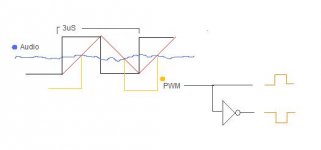
The "audio signal" in your drawing has -20dB of 10Mhz content...
Wrong example to prove a wrong knowledge system.
Triangle wave modulation leaves many problems unsolved, namely a cumulative error from the previous cycle to the next that takes several cycles to be corrected. And it adds an input-to-output delay equal to the clock period. That's why triangle-wave modulators need a quite high clock to get some accuracy.
There are better approaches that leave little or no cumulative errors for the next cycle, all involving non-linear modulation (integration and convergence). These give better accuracy with a lower clock.
Understanding that may require updating your knowledge system.
To EVA:
I draw this simple design with paint ... just to show the application of the clock.
why do you answer me something else?
please, answer what and how it should be the clock to get the same result with AD (if you think that you can get)
ok .. audio signal is a line (no noise).
not explain what is better or worse. just answer the question.
if you have a deep knowledge (not just theoretical bla bla ..), then you can respond in 10 sec.
the question that I made you discover many things.
To Juhleren:
Yes, you are not specialist.
Believe it or not, the square wave before the filter contains all the audio frequency components with the right amplitudes. In fact, the filter has to be designed to leave these components intact, and attenuate only the frequency components above audio frequencies, which both speakers and our ears ignore.
Eva, yes i know and i don´t claim to be one either, but do you claim to be one??
I have never heard of a filter that can do what you describe. Filters are always causing phase distortion along with their attenuation, hence they build up energy (this side effect comes in handy when pulsing high speed bursts in to a `slow´filter, as the bursts are absorbed and released by the filter as an average amplitude being of lower or at the ringing frequency of the filter)... As we are talking about PWM, no? The width of the pulses are the variable, and the amplitude is given, no? -So how can the amplitudes be `the right amplitudes´ as you claim (you ment in the right proportion, no)? Maybe you got a different taste in music, but my collection usually have different and very varying amplitudes, and i also like to adjust the volumen once in a while
Where do you get these ideas from(measurements, writings, own ideas), can you be more elaborate, or are you just saying things for fun?
cheers,
Eva,
Apparently you are the specialist, so we are eager to learn from you.
What I recall from earlier times however is that teachers which were arrogant and did not respect the "ignorance" of their pupils were not very popular.
So try to move your tone a bit in a more friendly direction; thank you.
Apparently you are the specialist, so we are eager to learn from you.
What I recall from earlier times however is that teachers which were arrogant and did not respect the "ignorance" of their pupils were not very popular.
So try to move your tone a bit in a more friendly direction; thank you.
Eva,I had no doubt that you would have responded to all .. except that the question that I did.
every opportunity we can to tell me that I do.. not understand,.. I do not know.
I think that you Have only selective theory in mind. does not allow you the flexibility to design or just find new solutions.
So .. do not tell others, who do not understand.
Perhaps you confuse the real work of engineering.
- Status
- This old topic is closed. If you want to reopen this topic, contact a moderator using the "Report Post" button.
- Home
- Amplifiers
- Class D
- I haven't played with class D in a while, are we at PASS level yet?