That is totally right! 🙂the interesting thing is that there is no strict distinction between "ported bass reflex" and "mass loaded transmission line".
in my case the TL is very short and basically just separates the driver from the port. I did not notice any relevant change of tuning frequency and output level (except for the badly overdampened version).
In fact, you can basically just "morph" a TL into a BR or vice versa.
Or another way of looking at it, is that a TL is just a less efficient BR.
Purely seen from how effective they work in a certain amount of volume (for lack of a better description)
Purely practically speaking, this is also exactly what I do when I have to find dimensions for a TL system.
First model it like a BR, add about 20-40% more volume (as in dimensions) and than try to make it all fit and move stuff around.
We are talking about different things hereUsually, both styles are more efficient per a given voltage than a regular BR enclosure.
We established this dilemma in another thread.the interesting thing is that there is no strict distinction between "ported bass reflex" and "mass loaded transmission line".
in my case the TL is very short and basically just separates the driver from the port. I did not notice any relevant change of tuning frequency and output level (except for the badly overdampened version).
72" or greater length port equals a transmission line.
@stv
Btw, for an acoustic low-pass we'll probably need some damping material in higher Sd section.
While still having the general path just open and free.
As a rough estimate with a BR port with a Sd of say 26cm² = 5.75cm diameter, we expect a standing wave around 3kHz already (vertical direction that is, NOT the length of the port)
Since the Sd of the lowpass section will be even bigger, this frequency will go down.
It would be interesting to see what happens if we match this with a certain ratio of the wavelength of the first mode of the port itself.
They might be able to cancel each other out! 🙂
I think we need to be careful making assumptions about what causes the changes in port response for the 'TL'. The cabinets internal geometry and modal pattern will be significantly changed as the enclosure is now divided (essentially half as deep and twice as long). Therfore the placement of the port and woofer relative to the cabinet modes also changes.
The propottion of the observed effects related to having more damping material vs modal pattern change is difficult to approximate, I think.
P.S. are we sure the TL has a low pass effect in of itself, when the only exit is via a BR? Does it really behave like two series low pass filter?
The propottion of the observed effects related to having more damping material vs modal pattern change is difficult to approximate, I think.
P.S. are we sure the TL has a low pass effect in of itself, when the only exit is via a BR? Does it really behave like two series low pass filter?
Last edited:
RTA graphs of tuning frequency port output
here are the "chuffing"/"noise"/"distorsion" RTA graphs for the mentioned ports.
these images visualize intuitively
- chuffing at port resonances
- low frequency noise once the inside/outside directed flow separate
- general noise of turbulent air flow
I will provide more easily digestible and comparable graphs in my next message!
one general comment: once there is visible noise in the spectrum the port is already unusable for serious music reproduction. the most annoying noise is port resonance chuffing, followed by wide range noise.
the low frequency noise is not as noticeable by itself, but it's always correlated with heavy compression, which makes noise and distorsion VERY audible!
1) tube port
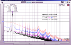
port resonance chuffing (760 Hz, refer to response graph above!) and general noise start at low levels. no sudden "collapsing" of output and quite good high level compression.
2) small port
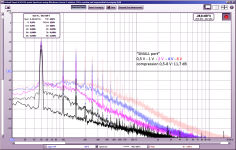
very characteristic low frequency noise starting at low levels, indicating flow direction separation. heavy compression. no resonance chuffing.
this port is unusable for any signal above 0,5 - 1 V.
3) medium port
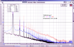
no resonance chuffing. rather low compression (this port is slightly more tubular than the next one!). seems usable up to just below 4 V.
3a) medium port with "caps" on both ends
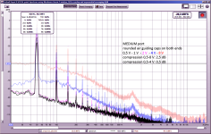
some resonance chuffing at high levels. I think this is caused by the two facing surfaces at both port ends. slightly less compression.
I will provide H3 distorsion graphs in the next post. H3 reduction is the most obvious benefit of "caps".
however the positive effects of caps are only apparent at very high levels, far above usable for high quality music reproduction.
4) big port
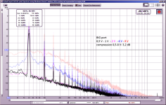
a very small sign of port resonance chuffing at 8 V (port length/diameter ratio is "worse" than small and medium port). a bit more compression than the medium port. however, that relates only to un-musical levels.
as I will explain in my next posts the small, cheap, and spec wise outdated monacor SP60 driver cannot provide sensible output above 3,5 V in the bass range. thus it seems ok to use a port that starts "collapsing" already at 4 V, just for this investigation case.
At these higher frequencies I think any "corner" has a lowpass effect.P.S. are we sure the TL has a low pass effect in of itself, when the only exit is via a BR? Does it really behave like two series low pass filter?
A very unfortunate problem here is that Hornresp doesn't have enough sections to model these things 🙁
I bet it can be done with Akabak as well
I bet it can be done with Akabak as well
The dampening tool (in the loudspeaker wizard) is extremely useful! You should use it, if you design a 2-way ported speaker!
You should not put dampening material between driver and port, however.
Is this right way round? A reasonable chunk of light damping placed between the driver and port will offer little resistance at the low Helmholtz resonant frequenciy but high damping at midrange frequencies hence reducing midrange leakage significantly. It needs to be kept away from the port mouth because of the high velocities in the vicinity.
Now would seem a good time to check which is the more effective approach although egg crate foam might not be suitable. BAF-type wadding may be preferable if you have something of the kind knocking around.
I've been trying to get that 5th segment for years!A very unfortunate problem here is that Hornresp doesn't have enough sections to model these things 🙁
I bet it can be done with Akabak as well
You might be able to get more than 5 segments with the PH functions for Paraflex (BP6S) enclosures.
I don't know if those PH functions will allow you to use them on direct radiator enclosures.
You can use Vtc & Atc as a compression chamber for a possible 5th segment...
Vtc & Atc = enclosure volume.
Ap1 & Lp = segment 1 port.
S1-S2 & L12 = segment 2 port.
S2-S3 & L23 = segment 3 port.
S3-S4 & L34 = segment 4 port.
S4-S5 & L45 = segment 5 port.
I might be wrong, but as far as I know, the interaction between enclosure volumes and the rest of the TL will be different.You can use Vtc & Atc as a compression chamber for a possible 5th segment...
Vtc & Atc = enclosure volume.
So we really want the entire line in more sections, because the position of the woofer + damping material is also gonna play a role in the entire line.
Also could you maybe make the pictures a little smaller (or as a mod to do it), because it's a bit overwhelmingly big atm?
relating the strouhal number to compression and distorsion
here is the data collected in the RTA measurements, processed in a more easily readable way.the most revealing graphs:
- strouhal number, calculated for the port variants at respective input voltages (referring to port exit radiusses).
- compression ratio (dB), referred to the lowest input signal
- 3rd harmonic distorsion
some observations:
- the graphs don't have many data points (0,5 - 1 - 2 - 4 - 8 V, additional 5,66 V for selected compression graphs). so there is some interpolation going on.
- tube port, as mentioned earlier (also in the papers), starts compressing early, but there is no sudden "collapsing of output". also H3 increase does not get steeper after strouhal number dropping below 1.
- 3rd harmonic seems to be particularly revealing regarding the usable output / input range. sensible output range should stay below 1% H3
- H2 distorsion is not reliable with nearfield measurement - if I'm not mistaken. also H2 will not be musically annoying.
- the "capped" medium port variant does not have a separate strouhal number. I'm not (yet) sure if and how to calculate a number based on the exit surface...
- "capped" port seems to behave quite well, but H3 and noise is still better with the "big" port - in the usable range of strouhal number above 1.
- I chose input voltage as X-axis reference, that's mostly just for convenience.
That's how this site is pasting the pics.Also could you maybe make the pictures a little smaller (or as a mod to do it), because it's a bit overwhelmingly big atm?
Keep in mind that none of those TL diagrams are mass loaded - which we are discussing here in this thread about ports.
Hope it's ok to ask to keep it that way.
If Vtc is big enough to mount the driver and the other 5 segments were smaller than Atc, then why would that TL not mass load in a stepped scenario?
Example:
Vtc & Atc = 12" H x 12" W x 6" L.
Ap1 & Lp = 6" x 12" x 16".
S1-S2 & L12 = 5.5" x 12" x 16".
S2-S3 & L23 = 5" x 12" × 16".
S3-S4 & L34 = 4.5" x 12" x 16".
S4-S5 & L45 = 4" x 12" x 2".
From what you are saying, there cannot be ANY venting directly behind the driver in order for mass loading to work.
Thats not what I meant.From what you are saying, there cannot be ANY venting directly behind the driver in order for mass loading to work.
The "TL" separation makes sense to reduce enclosure resonance effects exiting the port.
No. If you click "insert into message" you can change the size, or just simply do that before you upload.That's how this site is pasting the pics.
- Home
- Loudspeakers
- Multi-Way
- Investigating port resonance absorbers and port geometries