*[Moderator edit at member request. This post has been superseded by post #595 - https://www.diyaudio.com/community/...rbers-and-port-geometries.388264/post-7697685 ]
The speakers will mostly be used for low level music reproduction in a small room. Also, the sensitivity is not bad for such a small driver. There is no shorting ring but as far as I understand the low voice coil overhang keeps inductance low.
I first define the maximum sensible input voltage for the small 4” midwoofers Xmax of 2 mm in the usable frequency range (above tuning freq).
I use a hornresp simulation tuned accordingly using a simple tube port and adjust the input voltage to keep displacement near Xmax:

of course the excursion will exceed Xmax below tuning frequency, but that’s to be expected with a ported box and such a low Xmax and Sd woofer.
This loudspeaker will not play loud and not very low.
3,3 V equals not even 3 W at 4 Ohm!
I would like to get (mostly) uncompressed and non-chuffing port output at the determined max. sensible input voltage, thus the Strouhal number should never go below 1 (one) with 3,3 V input.
(refer to post #503 for details on strouhal number calculation!)
Thus the requirement is:
The maximum air particle displacement (and air speed) in the port happens at tuning frequency (fb), which in my case is around 50 Hz.
particle displacement can be calculated using the max. airspeed value from a simulation (see #391):
so for the Strouhal requirement:
we can postulate:
It is now either possible to
For my speaker I start with a 5 cm diameter tube port (19,6 cm²) and get the following result:

Max airspeed = 6,57 m/s
The displacement is higher than the port radius, even at tiny 3,3 W input and a “generous” (so I thought) 5 cm port, thus the Strouhal number is below 1 (indicating potential flow separation):
Increasing the port diameter will raise the port radius proportionally but also reduce the air speed by division through square of the increase factor (because of squared increase of port cross section surface).
Note that this is just an approximate method, assuming uniform air movement in the port therefore it’s important to use sensible entry data. As far as I know hornresp does simulate realistic air movement in the port!
Thus an increase of port diameter or radius by factor x will increase the Strouhal number by x³.
We have a Strouhal number of 0,60 and need a Strouhal number of 1, thus:
To get x (port radius increase factor) we need to calculate the cubic root of x³:
The required minimum effective port exit diameter is
This diameter refers to any port form. While it is also valid for tube ports these don’t show any sudden change of port behaviour when going below a Strouhal number of 1. Tube ports behave worse than flared ports at low displacement levels and better at higher levels.
I suggest to focus on the low displacement levels relevant for high quality music reproduction.
how to find a suitable port exit diameter using the Strouhal number
For my 2-way speaker the goal was to use the old drivers I already had, even if they are quite outdated spec-wise. These drivers and speakers have a sentimental value, and I challenged myself to get the best out of them.The speakers will mostly be used for low level music reproduction in a small room. Also, the sensitivity is not bad for such a small driver. There is no shorting ring but as far as I understand the low voice coil overhang keeps inductance low.
I first define the maximum sensible input voltage for the small 4” midwoofers Xmax of 2 mm in the usable frequency range (above tuning freq).
I use a hornresp simulation tuned accordingly using a simple tube port and adjust the input voltage to keep displacement near Xmax:
of course the excursion will exceed Xmax below tuning frequency, but that’s to be expected with a ported box and such a low Xmax and Sd woofer.
This loudspeaker will not play loud and not very low.
3,3 V equals not even 3 W at 4 Ohm!
I would like to get (mostly) uncompressed and non-chuffing port output at the determined max. sensible input voltage, thus the Strouhal number should never go below 1 (one) with 3,3 V input.
Strouhal number = port radius / p-p air particle displacement
(refer to post #503 for details on strouhal number calculation!)
Thus the requirement is:
port radius ≥ p-p air particle displacement
The maximum air particle displacement (and air speed) in the port happens at tuning frequency (fb), which in my case is around 50 Hz.
particle displacement can be calculated using the max. airspeed value from a simulation (see #391):
p-p air particle displacement [m] = max. airspeed [m/s] / (Pi * f[1/s])
so for the Strouhal requirement:
port radius ≥ p-p air particle displacement
we can postulate:
Max air speed [m/s] = port radius [m] * Pi * fb [1/s]
It is now either possible to
- approximate the required max. airspeed in the simulation tool by adjusting the port surface in the simulation while considering the updated port radius.
- or it’s possible interpolating the value found with sensible starting parameters:
For my speaker I start with a 5 cm diameter tube port (19,6 cm²) and get the following result:
Max airspeed = 6,57 m/s
p-p particle displacement = 6,57 [m/s] / 3,141 * 50 [1/s] = 0,042 m = 4,2 cm
The displacement is higher than the port radius, even at tiny 3,3 W input and a “generous” (so I thought) 5 cm port, thus the Strouhal number is below 1 (indicating potential flow separation):
Strouhal Number = 2,5 cm / 4,2 cm = 0,60
Increasing the port diameter will raise the port radius proportionally but also reduce the air speed by division through square of the increase factor (because of squared increase of port cross section surface).
Note that this is just an approximate method, assuming uniform air movement in the port therefore it’s important to use sensible entry data. As far as I know hornresp does simulate realistic air movement in the port!
Thus an increase of port diameter or radius by factor x will increase the Strouhal number by x³.
We have a Strouhal number of 0,60 and need a Strouhal number of 1, thus:
x³ = 1 / 0,60 = 1,67
To get x (port radius increase factor) we need to calculate the cubic root of x³:
x = cubic root of (1,67) = 1,19
The required minimum effective port exit diameter is
1,19 * 5 cm = 5,95 cm
This diameter refers to any port form. While it is also valid for tube ports these don’t show any sudden change of port behaviour when going below a Strouhal number of 1. Tube ports behave worse than flared ports at low displacement levels and better at higher levels.
I suggest to focus on the low displacement levels relevant for high quality music reproduction.
Last edited by a moderator:
@Tenson
By "port exit diameter" I mean the effective opening diameter from port to the "outside".
have a look at post #526 regarding the "effective opening diameter" or radius, for strouhal number calculation.
The central narrowest part of the port is actually not that relevant - however there is probably a limit of useful air speed and respective air linearity.
As I tried to show and investigate, the crucial part of the ports is EXCLUSIVELY the transition from moving air zone to pressure variation zone and vice versa, thus the intake/exit. this is where all turbulent airflow, flow separation and noise generation happens and this is why we need a minimum cross section for useful ports (actually only for the intake/output).
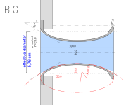
Using the BIG port (see plan in #529) as measured in the previous messages and the max useful input voltage (see above) here are the corresponding airspeeds and particle displacement distances:
the strouhal number is sligtly less than 1 at port terminations, because I have an effective diameter of 5,76 cm (28,8 mm * 2), but my calculation above actually gave a minimum of 5,95 cm!
the "strouhal number" (not sure whether it can be called so) in the central, narrow part is only 0,13 cm! But it's no problem, because there is no sudden change from directed flow to pressurized "open space".
the profile woul look very similar to the BIG port:

I will post a method for defining the geometry of such a port using:
but I'm still working on that!
By "port exit diameter" I mean the effective opening diameter from port to the "outside".
have a look at post #526 regarding the "effective opening diameter" or radius, for strouhal number calculation.
The central narrowest part of the port is actually not that relevant - however there is probably a limit of useful air speed and respective air linearity.
As I tried to show and investigate, the crucial part of the ports is EXCLUSIVELY the transition from moving air zone to pressure variation zone and vice versa, thus the intake/exit. this is where all turbulent airflow, flow separation and noise generation happens and this is why we need a minimum cross section for useful ports (actually only for the intake/output).
Using the BIG port (see plan in #529) as measured in the previous messages and the max useful input voltage (see above) here are the corresponding airspeeds and particle displacement distances:
effective radius | effective surface | particle velocity (at 3,3 V) | p-p particle displ. (at 3,3 V) | strouhal number | |
| port exit/intake (port ends) | 2,88 cm | 26,06 cm² | 5 m/s | 3,18 cm | 0,9 |
| central port section | 1,5 cm | 7,07 cm² | 18 m/s | 11,46 cm | 0,13 |
the strouhal number is sligtly less than 1 at port terminations, because I have an effective diameter of 5,76 cm (28,8 mm * 2), but my calculation above actually gave a minimum of 5,95 cm!
the "strouhal number" (not sure whether it can be called so) in the central, narrow part is only 0,13 cm! But it's no problem, because there is no sudden change from directed flow to pressurized "open space".
the profile woul look very similar to the BIG port:

I will post a method for defining the geometry of such a port using:
- exit diameter for keeping strouhal number above 1
- exit flare of 30°
- required port length for resonator tuning
but I'm still working on that!
Last edited:
Thats not what I meant.
The "TL" separation makes sense to reduce enclosure resonance effects exiting the port.
Can you explain how this TL is not mass loaded?
It's a rather semantic discussion, in the physical sense there is no absolute distinction.Can you explain how this TL is not mass loaded
"Mass loaded" in this case means there is an air mass inside a (small) port, being excited by the propagating wave in the transmission line.
The advantages are that you have additional freedom to chose the port location along the resonator. And the mass loading can lower the resonance far beyond the actual quarter wave length.
You should really read through the entire thread again - it's all about what is really happening beyond the common rules of thumb!How about no less than 1/3 of Sd?
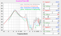
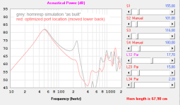
here is a very quick and rough hornresp simulation with measurement overlay of my mass loaded TL test:the TL length resonance at 265 Hz could probably be eliminated or very much reduced by optimizing the line geometry and, more importantly, correctly positioning driver and port along the transmission line.

the TL length resonance is higher in reality, but the rest fits quite well.
due to folding of the line the higher resonances are less prominent in the measurement.
I should add that the resonance peak was not steep enough with the standard setting of QL=7.
I set it to 17 in the image above - is this effect of a perfect (low-loss) port?
the steeper low frequency rolloff is caused by the out of phase signal from the driver.
The complete isolation of hornresp's port output cannot easily be replicated in the measurement.
and by just moving the port down by 12 cm (towards the driver) the TL length resonance can be eliminated:

I'd have to check this solution in reality, but it seems to be incredibly easy - much too easy not to follow this path.
and the "TL" boards have an additional bracing benefit!
Last edited:
I think I get where you are coming from.
The mouth in pic D needs to be a couple inches off the bottom of the enclosure in order to achieve true mass loading.
MLTL's are a PITA to model. Ap needing to bigger than S1-S4 was throwing me off.
Internally, the enclosure is 108" high x "18.5" wide x 10" deep.
The port is 14" high x 14" wide x 0.75" deep.
Single fold with the above rear firing port = 55.5" high x 20" wide x 22.25" deep externally.
Double fold with the above rear firing port = 28.5" high x 20" wide x 43.75" deep externally.
Trifold (?) with the above above rear firing port = 37.5" high x 20" wide x 33" deep externally.
I see moving the port up 8" changed the upper resonance. It also gained SPL at the expense of port velocity.
Okay thanks, I see now. I'm too used to starting by defining the middle dia. of the port and then flaring it by an amount to define the exits; I thought you were actually going to use a 5cm port diamterer because you defined it early on just as I normally would.@Tenson
By "port exit diameter" I mean the effective opening diameter from port to the "outside".
have a look at post #526 regarding the "effective opening diameter" or radius, for strouhal number calculation.
The central narrowest part of the port is actually not that relevant - however there is probably a limit of useful air speed and respective air linearity.
As I tried to show and investigate, the crucial part of the ports is EXCLUSIVELY the transition from moving air zone to pressure variation zone and vice versa, thus the intake/exit. this is where all turbulent airflow, flow separation and noise generation happens and this is why we need a minimum cross section for useful ports (actually only for the intake/output).
Using the BIG port (see plan in #529) as measured in the previous messages and the max useful input voltage (see above) here are the corresponding airspeeds and particle displacement distances:
port exit/intake (port ends) central port section
the strouhal number is sligtly less than 1 at port terminations, because I have an effective diameter of 5,76 cm (28,8 mm * 2), but my calculation above actually gave a minimum of 5,95 cm!
the "strouhal number" (not sure whether it can be called so) in the central, narrow part is only 0,13 cm! But it's no problem, because there is no sudden change from directed flow to pressurized "open space".
the profile woul look very similar to the BIG port:
View attachment 1316346
I will post a method for defining the geometry of such a port using:
- exit diameter for keeping strouhal number above 1
- exit flare of 30°
- required port length for resonator tuning
but I'm still working on that!
I see now that could be almost any number and is only a means to extract the strouhal number and the adjustment factor.
Your method is to define the exit diamterer and a flare rate / profile. This way the center diamterer comes out 'automatically'. Which as you said is sensible as the exits are where the noise comes from.
Wouldn't it be nice if this method was built in to software like Hornresp or WinISD
I think the key to MLTL is that there is an additional tuned section (the mass) at the output of the first TL. Kind of like two TLs in series. That additional mass could be a BR port or a narrower TL. Essentially it provides a higher acoustic impedance to Unload the energy from the first line, kind of like you can put more energy from your arm in to throwing a heavy ball than a super light one.
One could argue though, that any cabinet is a TL and a BR is the additional mass placed at any point along it. You could just unfold a TL, call it a tall narrow box and ads a BR port.
That's what I was saying in another thread, that a TL was nothing more than a fancy BR.
I asked the question at what length does a BR becomes TL. 72" was chosen and then backed up by the David B. Weems book from 1990.
Truthfully, I could care less about any direct radiator enclosure. Bandpass for life!
I like this thread because bandpass enclosures can benefit from the research even though I would never buy a tube port when I can make a slot port from spare wood with a flare at the throat and mouth.
Strouhal number = port radius / p-p displacement
Shouldn't the formula be as shown below?
Strouhal number = 2 * port radius / (pi * p-p displacement)
Why not just use:
Strouhal number = port diameter * frequency / particle velocity
Am I missing something, perhaps?
Hello @David McBean ,
have a look at the roozen paper:

any chance to include strouhal number calculation into hornresp?
But I know, it's probably not going to happen
have a look at the roozen paper:
any chance to include strouhal number calculation into hornresp?
But I know, it's probably not going to happen
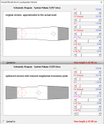
here it is, also the "optimized version"!do you mind showing the hornrsp system schematic?
I tried to follow the "centerline" unfolding technique.
attached also the hornresp record of the original version, just in case.
I should add that there is still a small wiggle in the combined frequency response.

Attachments
have a look at the roozen paper:
Thanks for the reference. It is interesting that the definition given in the paper is somewhat different to the one that is normally used.
any chance to include strouhal number calculation into hornresp?
I would first need to establish what formula to use.
See the calculator site linked below (characteristic length = port diameter):
http://www.calculatoredge.com/mech/strouhal.htm
- Home
- Loudspeakers
- Multi-Way
- Investigating port resonance absorbers and port geometries