R15=2k2In the figure, a different connection point is selected

![DSCN0302[1].JPG](/community/data/attachments/1082/1082446-a0d2dd500f8ad93326dd1cb27c51275d.jpg)
Actually he buiilt a stereo amp using 2 heatsinks.Is there any reason for which JLH proposed dedicated heatsink for each transistor? Practically i don't see any advantage of doing so.
JLH used one sink per channel. Surprisingly he did not mention the thermal resistance nor type of heatsink (IIRC).Is there any reason for which JLH proposed dedicated heatsink for each transistor? Practically i don't see any advantage of doing so.
Nelson Jones suggested using one sink per transistor. If directly mounted, that saves at least 0.5C/W. Obviously using one sink per transistor (at 2.2C/W) will give an effective thermal resistance of 0.55C/W, the value suggested by Ian.
If JLH's heatsinks were common (back then) 10D, 100mm at 2.2C/W, adding 0.5C/W for the mica washer insulator (with silicone paste) and the thermal resistance of the transistor, that's 2.5C/W for the transistors at 16.2W =44C plus 2.2C/W for the whole 32.4W = + another 71.8 degrees. That's 71.8 above ambient, so could be nearly 100C, and junctions 116 above, or maybe 140C. That's a bit warm. Current safety standards say anything over 50C needs to be provided with a protection of some sort so as to prevent touching. It isn't clear, either, if JLH ran his unit with an open top or with a slotted lid on - the type of box, an aluminium diecast by the look of it - would have had a matching lid but not shown. There appears to be slots in the base for air flow, but I suspect the box may have got quite warm after a while. JLH's box and sinks may have been 150mm long - the unit is foreshortened due to the vertical orientation of the shot, so somewhat hard to be sure.
Using modern transistors with higher power rating will have a lower thermal resistance from chip to case than 2C/W of the original MJ481. But modern plastic devices may also be limited in maximum junction temperature than 200C.
In short- one sink per transistor can allow direct mounting, saving a thermal resistance, but has the problem of each sink having to be insulated.
A single sink for stereo needs a low value of thermal resistance to hold the transistor temperature to a reasonable value.
In the early days, RCA made a point of publishing thermal cycling data for their transistors. This is related to the thermal expansion/contraction per use cycle leading to eventual deterioration or failure. Recent figures for this are not widely available (at least to my knowledge) but the lower the temperature of your junctions, the longer transistors will last.
I'm thinking of alternative heatsink arrangements for people like me, who no longer have a workshop with machine tools or maybe any kind of tools that can cut thick metal. i.e. hacksaws, power drills, shears etc. It's rather restrictive so the cost of complete boxes from China, which either incorporate or allow for large heatsinks in their construction, is tempting, but will this work for us?
Mass-produced boxes with the heatsinks incorporated into the side or front panels, can perform both structural and cooling roles. This saves space, can be considerably cheaper and frees up the front and rear panels for whatever controls , indicators and connectors you want. The link below is to the smallest size box with side heatsinks, that I could find. When fully warmed up to a stable temperature, I doubt it would suit a full 10-15W build but it may be useful for a pair of mini-JLH amplifiers that may have been modified for a little more power. There are larger sizes and more styles of such boxes to choose from anyway. This is just the smallest: https://www.aliexpress.com/item/330....order_list.order_list_main.10.21ef1802Lqt0wm
Question: As the power transistors probably should have extended leads for best heat distribution , how tolerant might the amplifier be to that?
Hello there,
My heatsinks arrived

They'd got holes for just one transistor so I started to file out the other holes, there were a couple of plastic bungs with wire in each of them. I can drill the rest of them out.
They are 125 square a little larger than the ones JLH used, otherwise very similar. Somewhere I've got an alloy sheet that I can cut to make a chimney. Many thanks to Ian for explaining what it was for.
More eventually.
Cheers - J
My heatsinks arrived
They'd got holes for just one transistor so I started to file out the other holes, there were a couple of plastic bungs with wire in each of them. I can drill the rest of them out.
They are 125 square a little larger than the ones JLH used, otherwise very similar. Somewhere I've got an alloy sheet that I can cut to make a chimney. Many thanks to Ian for explaining what it was for.
More eventually.
Cheers - J
Without wishing to spoil your fun, how do you plan to fit 2 transistors to (apparently) the same mounting bolt? Perhaps you're going to shift the second transistor down to another position as well? good luck with that, because you should be using an accurate drill size and hole location for that work.
Note that the "bung" is probably a flanged insulator bush (buy from any components seller) and one should fit neatly in each of the transistors mounting holes, providing insulation for the bolts which would otherwise short the transistor collector to the heatsink (likely ground) and probably kill the power supply. Aternatively, if they are plain bushes, located in the same holes as base and emitter leads, theyre just insulation or aids to fitting them. One of the bolts will also require a small solder tag in order to make a a connection to the collector.
Note that the "bung" is probably a flanged insulator bush (buy from any components seller) and one should fit neatly in each of the transistors mounting holes, providing insulation for the bolts which would otherwise short the transistor collector to the heatsink (likely ground) and probably kill the power supply. Aternatively, if they are plain bushes, located in the same holes as base and emitter leads, theyre just insulation or aids to fitting them. One of the bolts will also require a small solder tag in order to make a a connection to the collector.
Last edited:
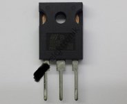
Hi.What about BD249C.Are they better than TIP35C ? I can supply for my JLH projects 8pcs.It is hard to supply TIP3055 here.
I also love TO3 but it is hard to drill for me. Plastic ones only needs one drilling. TO3 needs 4-5 drilling per transistor.
I also love TO3 but it is hard to drill for me. Plastic ones only needs one drilling. TO3 needs 4-5 drilling per transistor.
Attachments
Last edited:
From a datasheet, BD249C looks OK and handles 10 times the current you need. In most respects other than gain (hFE), it is adequate but they will be Multicomp products (several sources and specs, including ISC) and TIP35 is usually to an ST Micro spec. We have discussed these recently and they are probably your best option. These may also be somewhat variable but they can be bought from many distributors at fair prices
The datasheets for your sources may not match with original specs and whilst not necessarily fakes, it is difficult to know what you have available and whether they are genuine to any spec. at all or just their own manufacturers spec. It's difficult to say at this distance, what your options really are.
The datasheets for your sources may not match with original specs and whilst not necessarily fakes, it is difficult to know what you have available and whether they are genuine to any spec. at all or just their own manufacturers spec. It's difficult to say at this distance, what your options really are.
Last edited:
It is advantageous to place radiators outside the main volume with electrical insulation and a protective grille (from burns)))Is there any reason for which JLH proposed dedicated heatsink for each transistor? Practically i don't see any advantage of doing so.
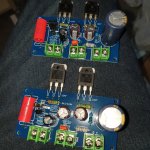
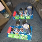
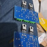
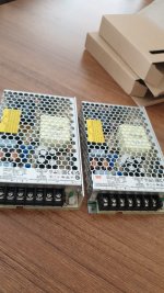
I have soldered the kit. There was 2 caps which i did not like 100uf 50v sam young ( i put panasonic fr ) and output capacitor Decon brand 3300uf 50v i have used Panasonic Fc 3300uf 35v. I have soldered output transistors like that. I hope there wont be any problems. It works at 24v. I also bought meanwell lrs150-24 . Maybe i can lower it to 21v for my 4ohm speakers.
Attachments
Veysel - I take it that you used your BD249's?
They seem to be much the same as TIP35 - essentially a European registration of the TIPs.
One minor difference is that the 15A current gain is lower - so it also allowed the manufacturers (not sure if TI registered the BD249 or a company that bought the manufacturing line (Power Innovations (is this the same Power Innovations still going?) as the transistor dept went to Bourns next)) to sell some TIP35 chips that didn't meet the TIP spec., I guess.
Ian - yes, good question. For 3-4MHz transistors I can only regurgitate the advice Bailey mentioned which is to keep leads to 4 inches or less, but if longer, add decoupling capacitors next to the transistor. For 30MHz devices it will be even more critical, though in the 2SC5200 and MJL3281A tests I ran these were mounted on a Redpoint 5.5R (or might have been W, can't recall exactly) which was approx 4x4 inch square,, 5.5 inches long and had radial fins each end of the centre section, so the leads to the PCB were about 4 inches, and only one of the types needed a 33pF compensation capacitor., otherwise both stable but the main smoothing capacitor was part of the PCB assembly.
Hi. I used 2sd718 of the kits. I will use bd249c instead of mini jlh circuit which has tip41c.Veysel - I take it that you used your BD249's?
They seem to be much the same as TIP35 - essentially a European registration of the TIPs.
One minor difference is that the 15A current gain is lower - so it also allowed the manufacturers (not sure if TI registered the BD249 or a company that bought the manufacturing line (Power Innovations (is this the same Power Innovations still going?) as the transistor dept went to Bourns next)) to sell some TIP35 chips that didn't meet the TIP spec., I guess.
Good work, glad you like the sound, with SMPS too! So, did you try both channels on the same supply to see if you could hear any difference? I have tried that with many transformer power amps - sometimes I can't pick any significant difference to separate supplies. Other comparisons show some obviously different stereo effects for reasons we may not have realised.
Regarding preamps; some people get a better, more consistent match of their source signal(s) to the amplifier if they use a preamp. and of course, it's a good place to add lots of other features and balance input and output levels to other devices such as mixers, subwoofers, recorders, headphone amp, ADC etc.
Personally, I prefer it simple if the impedance match is good enough to begin with. Sometimes it just isn't but a preamp that adds a bit of gain and control without loading the source or increasing the noise level, is just right and allows your system to sound better to some degree but sometimes it doesn't and you waste time and money on something unnecessary.
B1 buffer is recognized as a great first preamp and a cheap kit of parts won't break the bank but a proper metal shield case, power supply, premium components, connectors and and good quality controls, won't be cheap. The Mezmerise development of the B1 (there are lots of builder variations) seems to be better though I've never listened with it.
- Home
- Amplifiers
- Solid State
- JLH 10 Watt class A amplifier