Pardon for newbie suggestion/question. Would a variable intensity laser cutting with proper cooling ventilation work ? That way the basket outer ring or remaing structures (Magnets etc.) remains intact with no dust/metal fillings. Various intensity laser can cut through horizontal surface to required depth or cut through and through hole.I have ordered two more visaton BG20-8 drivers. <snip>
Regards
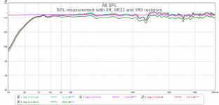
A series resistor effect
There was a suggestion in this thread, that a small resistor in series with a speaker might reduce acoustical distortion.
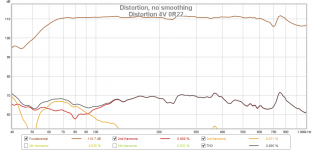
With my SS amplifier, speaker and setup, I could not support this idea and could not repeat such result. I measured distortion at 4Vrms, with 0 ohm, 0.22 ohm and 1 ohm resistors in series with speaker. Amplifier output impedance is 0.026 ohm, plus there is a speaker cable impedance (6m 2x4mm^2). The only effect was a change in frequency response (expected) and slight change in level as expected from the resulting impedance dividers. Plots of SPL and distortions attached. Very small reduction of distortion with resistors reflects the level change with resistors.
There was a suggestion in this thread, that a small resistor in series with a speaker might reduce acoustical distortion.
With my SS amplifier, speaker and setup, I could not support this idea and could not repeat such result. I measured distortion at 4Vrms, with 0 ohm, 0.22 ohm and 1 ohm resistors in series with speaker. Amplifier output impedance is 0.026 ohm, plus there is a speaker cable impedance (6m 2x4mm^2). The only effect was a change in frequency response (expected) and slight change in level as expected from the resulting impedance dividers. Plots of SPL and distortions attached. Very small reduction of distortion with resistors reflects the level change with resistors.
Attachments

Last edited:
Makes not much sense because FR is affected by a resistor. Make "constant" at one frequency point changes another point. I suppose that any judicious person can read and compare SPL/distortion and would not suggest that there is an audible change in distortion. However, we may speculate about FR change audibility, because insertion of 1ohm resistor makes 1dB change in FR profile and this may be audible, contrary to distortion change.
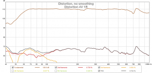
BTW, change in distortion at cursor frequency (175Hz) is 1.2dB and change in SPL is also 1.2dB. Distortion rises almost linearly with SPL (shown earlier), so there is no change in distortion with the 1R resistor compared to 0R.
Voltage distortion at speaker terminals, H2, is 0.004% without resistor and goes to 0.013% with 1ohm resistor, at the cursor point.
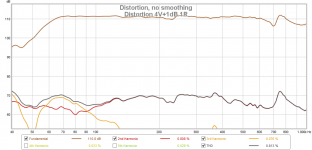
P.S.: added 1ohm measurement with 1dB added to 4V level to make "equal" SPL. See more bass about 65Hz, with exactly same distortion at 65Hz.
BTW, change in distortion at cursor frequency (175Hz) is 1.2dB and change in SPL is also 1.2dB. Distortion rises almost linearly with SPL (shown earlier), so there is no change in distortion with the 1R resistor compared to 0R.
Voltage distortion at speaker terminals, H2, is 0.004% without resistor and goes to 0.013% with 1ohm resistor, at the cursor point.
P.S.: added 1ohm measurement with 1dB added to 4V level to make "equal" SPL. See more bass about 65Hz, with exactly same distortion at 65Hz.
Attachments
Last edited:
As Richard discussed, was this what you did?There was a suggestion in this thread, that a small resistor in series with a speaker might reduce acoustical distortion...
Attachments

Have I mentioned Richard in conjunction with my test? If you think so, would you quote?
Again, it MUST make a noticeable (and audible) difference in frequency response and step response, if you use that high resistance as 2 - 4 ohm. It may make some distortion change in the part where impedance is low and comparable to 2 - 4 ohm. However, I would not suggest to use such high resistance, if your goal is not to make an effect box.
Oh, ok. I also tried series resistor, in that case 2- 4 ohm made a noticeable difference.
Again, it MUST make a noticeable (and audible) difference in frequency response and step response, if you use that high resistance as 2 - 4 ohm. It may make some distortion change in the part where impedance is low and comparable to 2 - 4 ohm. However, I would not suggest to use such high resistance, if your goal is not to make an effect box.
Experiments like this are interesting and I would suggest using my variable output resistance amp I posted a while ago.
As to current drive in whole or partial: what it does is fight those distortions that are caused by impedance modulation as a result of position and movement of the VC vis a vis the magnet assembly. This and only that. If I understand correctly, this is also the distortion mechanism JN is trying to correct.
From the experiments I have (seen) done, the improvements are marginal, if they exist at all, which leads me to believe that this impedance modulation is not a major constituent of loudspeaker distortions. Other trees are eminently more barkable.
As Richard discussed, was this what you did?
This does not work for me. Distortion of the amplifier is increased and output voltage swing is reduced, in simulation.
Edit: the inserted Rs reduces gain (quite significantly), so it also may reduce distortion for smaller amplitudes. However, the swing is reduced, power is reduced and full swing distortion is increased.
Attachments
Last edited:
That is what I found in sim, voltage distortion was increased while speaker current distortion was reduced. That was why I suspected that most amp designers are reluctant to adopt. The important fact often ignored is that Richard measured reduced acoustic distortion, remarkedly around resonance.... Distortion of the amplifier is increased and output voltage swing is reduced, in simulation...
The important fact often ignored is that Richard measured reduced acoustic distortion, remarkedly around resonance.
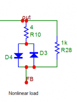
To me, this circuit as shown is tricky.
I have tried a simulated nonlinear load as attached. With a "normal" circuit connection, when load is referred to ground, distortion is very low and almost equivalent to 4ohm resistive load. With the suggested circuit, Rs=0.22 ohm and FB above Rs, voltage distortion goes up to 1%-10% (amplitude depend.) and current distortion is not improved.
Attachments
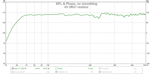
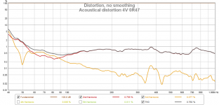
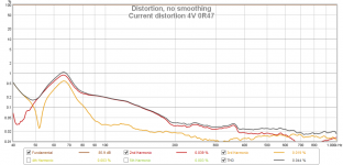
Another set of measurements, might be of some interest. Again 4Vrms, now 0R47 series resistance :
-SPL
- acoustical distortion
- distortion of speaker current
First, looking at distortion below 70Hz here is pointless, because H2 becomes higher than fundamental harmonics, which results in those big numbers. Low frequencies are emitted by the port (vent).
Second, we can see that around 70Hz (2nd impedance resonance peak) up to 100Hz approx. the current distortion is high and around 70Hz it is similar as acoustical distortion. Voltage distortion at amp terminals remains invisible in these plots, below the bottom of the graph. This (near 2nd resonance peak) is the area where current drive may help. However, I agree that the best way is to improve the speaker driver, rather than fiddle about feedbacks.
Attachments
I only tried the Stereophile speaker load model as shown before.
Yes but it is a linear model. Linear complex RLC dummy impedance. We are talking about nonlinearities that cause distortion of speaker. Not about linear RLC that may cause distortion of the amplifier. Amplifier distortion is assumed negligible and such must be in the experiment, to prevent mixing of apples and pears.
- Status
- Not open for further replies.
- Home
- Member Areas
- The Lounge
- John Curl's Blowtorch preamplifier part III