Yes, Belkin and Panamax and others started offering models derived from our research and well publicized topology and marketing story of the Monster products. The unit you show is a direct clone.The filtering looks to be not dissimilar to what you implemented and it worked as advertised in terms of reducing mains noise .
I now know how to eliminate or at least minimise ferrite sound so perhaps I rejected it too soon, someday I will experiment with different core materials including different ferrite formulations and powdered iron cores. .
Dan.
I am working with the original mfr of these in Bangkok which still produces many power products but not distributed in USA any more. Doing regional and via Internet sales.
I am working on newer designs and methods now.
THx-RNMarsh
Last edited:
Your original design must be good then.Yes, Belkin and Panamax and others started offering models derived from our research and well publicized topology and marketing story of the Monster products. The unit you show is a direct clone.

Care to name them ?.I am working with the original mfr of these in Bangkok which still produces many power products but not distributed in USA any more. Doing regional and via Internet sales.
Care to elaborate?.....in your original design what core materials did you use and where and why ?.I am working on newer designs and methods now.
Dan.
http://www.magnetaudio.com/?fbclid=IwAR1c6YS74V4XNSF7vS-lyfSmvlpDDguAgE6wcJw7KfvR2pS8f9ZPFOqL_AwCare to name them ?.
THx-RNMarsh
Ok thanks I have seen the Magnet site before, I forgot that was your production connection in Thailand, they seem very good.
Ok, so what's the low down on fuseholders, and Rhodium vs Gold plated fuse end caps, is the fuse element 99.99% OFC, what's the black coating etc ? I have heard differences regarding fuses so no counter arguments from me, what have you found ?.
Dan.
Ok, so what's the low down on fuseholders, and Rhodium vs Gold plated fuse end caps, is the fuse element 99.99% OFC, what's the black coating etc ? I have heard differences regarding fuses so no counter arguments from me, what have you found ?.
Dan.
i'll throw out a topic to see what/who bites ....
bob recently released his second edition.
maybe the members with high levels of industry expertise (is that diplomatic enough - just joking) who have read some of it can comment on topics of interest to them that us hobbyists can relate to?
maybe john has a comment or two like "xyz would have been nice to do to the blowtorch if I knew it or had that part back then; you guys should try it and here's why ... " or "my real-life experience over the years is that abc doesn't work so well in actual practice and here's why ..."
mlloyd1
Seems we need more magical cure topics to keep discussion going on ;-). Fairy tales about textbook engineering approach etc. ;-)
Mlloyd1, you make a great point. It is what this thread was continued for, but it has gone astray. I agree that 'exotic' fixes are only a small part of potential improvements, and just improving basic design choices and layout can make real gains.
The problem with this, are the continuing absolute statements, like: "All 'properly' designed power supplies are completely adequate", and other similar statements.
The problem is that it is often difficult to show a MEASURABLE improvement compared to a sonic improvement, because of the things we normally test for. Sine waves at a constant level, just don't cut it entirely. Then when we hear a difference, (in a power supply change for instance), we are challenged to PROVE our contention that there is an audible difference. Personally, I try to get around this, for myself, by having others, not necessarily related or dependent on me, hearing a similar difference as I have.
For the record I can say this: Some power supplies look great on paper, good visually, most probably measure well enough, BUT they can be extremely sensitive to power line 'stuff' riding on the 50-60Hz. This depends on location, of course, as some areas are cleaner than others. This is where power conditioners can make a big difference, but not for everybody. Richard is doing a great job of conveying his experience in this.
Ok, so what's the low down on fuseholders, and Rhodium vs Gold plated fuse end caps, is the fuse element 99.99% OFC, what's the black coating etc ? I have heard differences regarding fuses so no counter arguments from me, what have you found ?.
Dan.
If a fuse is to be useful it won't be copper. Real (UL certified) fuses have very specific overload thresholds and are quite consistent. I would not use a fuse that is not certified for a safety related application. There are Chinese vendors with knockoff fuses that have fake UL markings. You need to know your source and ideally supply chain to be safe. The "tuning fuses" are very scary. And at those prices I doubt they have sent thousands to UL for testing.
A gold flashed fuseholder may be wrong for a tin plated fuse cap. I remember pulling back computer PCB's with gold sockets and replacing them with boards with tin sockets because the gold contacts were degraded and unreliable with the tin plated pins on the IC's.
Having been to several post electrical fire inspections I would not take a chance on this stuff. The hazards are real. Fortunately none were Monster's fault. They still always blame the surge protector first and then look for a real cause.
There are many places where humidity and temp are always high. Bangkok, for example, is one of them. The typical copper/brass or tin contact does not stay stable and low. Gold for low R and stable contacts for a long time period is necessary in high humidity areas.
As for the various ferrite alloy compositions, you really need a network analyzer to know what to use for filters.
THx-RNMarsh
As for the various ferrite alloy compositions, you really need a network analyzer to know what to use for filters.
THx-RNMarsh
Last edited:
I think most of us know, but it should be stated, not Gold by itself. Gold on Gold is what is effective. No dissimilar metals, that partially is what Demian is alluding to. That would include rhodium on rhodium, nickle on nickle, etc.
And of course all the substandard flashing we see today.
Cheers
Alan
And of course all the substandard flashing we see today.
Cheers
Alan
Of course you all know lightning strikes nearby induce a CM signal. So, you convert CM to DM and then eliminate it via MOV. L401, C401-C402 perform transient spike signal conditioning before the MOV. This helps extend the life of the MOV and reduces let-thru. To see the whole picture, you cant look at a single component... a network analyzer and HV transient generator is needed for proper evaluation.
Since this is not a consumer forum so much as design issue forum, I will say that the protection is not only for transients from lightning but also taking into consideration sags and surges on the utility lines and how they are handled is part of the design.
On the models with special isolation transformers, the protection from transients is mostly for the circuitry within as no transients get thru the transformers. Demian Martin can attest to this as he did the UL type transient testing during prototyping.
Of course with or without the isolation transformers, the LP filters greatly attenuate any transients making the MOV's primarily in a surge protection roll, only. Except at the input as discussed above.
THx-RNMarsh


I believe aluminium wiring for domestic use is no longer allowed anywhere in the world. Its still used in distribution systems but that's a very different application.
Effective surge suppression is not a simple task and gets very sophisticated with subtle tweaks to PC layout on the less expensive products. The issue is that a surge (6000V with a 2 Ohm source Z or 3000A) rising at less than 10 uS getting limited to 300V or so. Without a surge generator you are only guessing what will happen.
What can be really challenging is that the low pass filter can ring and have more on its output than the input. That's why you find MOV's in numerous places in the Monster products.
Demian,
I'm glad that Richard posted the schematics here. Now you can have the one that he told me to not share with anyone. I'm trying to recall what you mentioned about the HTPS 7000 MKII, in page 1, 7D of he schematic. Something about the ST and the red wire in the upper right?
Richard,
You told me once that choke needed to be of which material formulation number...what is that number again?
Demian, Richard or Everyman:
(However I thought this next question was particular to only this model, but I could be incorrect.) In the HTPS 7000 (not the MKII) what is the issue if the ground lug gets broken off the main power plug? It's more than just grounding is it not?
Cheers,
Attachments
Last edited:
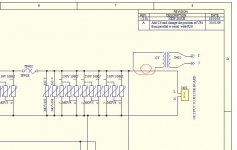
The item in the corner is a current transformer for the current measurement system. Its not drawn right and the red wiggle is supposed to show where its in the circuit I think. Also in the MK2 schematics the isolation transformers are missing. The key difference between MK1 and MK2 is that the center taps of the isolation transformers are switchable. You may get better performance with the center tab grounded or open. No way to predict really. And the GFCI's on the outputs are also not shown. The coax surge suppressors are missing the gas tubes. None of this should slow anyone down who could deal with one of these beasts.
If the ground pin is broken replace the connector or the cord. The filter capacitance to ground would be compromised with that open. Do not use this on an ungrounded circuit.
If the ground pin is broken replace the connector or the cord. The filter capacitance to ground would be compromised with that open. Do not use this on an ungrounded circuit.
Last edited:
For DM surges the MOVs shunt the surge. For CM surges opposed by L401 the MOVs are in series with the surge, they can only drop it's voltage by 150V or whatever their limit voltage is. And C401 lets any CM surge through anyway. So it's hard to see how this can be effective against CM surges unless they are low voltage surges.
Where is the CT switchable in the MKII? Also in the MKII Didn't multiple diodes replace the gas tubes? Or am I look at the schematic incorrectly. Wasn't there just one tube in the original and MkII with diodes?The key difference between MK1 and MK2 is that the center taps of the isolation transformers are switchable. You may get better performance with the center tab grounded or open. No way to predict really. And the GFCI's on the outputs are also not shown. The coax surge suppressors are missing the gas tubes.
Also in the MKII Didn't multiple diodes replace the gas tubes? Or am I look at the schematic incorrectly. Wasn't there just one tube in the original and MkII with diodes?
The gas discharge tube has lowest capacitance and also higher capacity. Its placement within the 75 Ohm cktry of pcb layout is critical for frequency response > 1Ghz without selective freq atten.
Others--- Dont ask for too many details as they wont be answered. Such as the make, P/N of the ferrites or their alloy make up. All circuitry is designed to work as one continuous filter over a wide BW. Nor details of the transformers or any other parts.
The audible effect of the noise generated by connected equipment as well as equipment from other hardware on-line being so thoroughly removed is quite remarkable. One needs to listen to their system with a thoroughly and IMHO well designed audio system power conditioner.
Note: There may be errors and/or omissions in schematic. It is suitable for trouble-shooting.
THx-RNMarsh
Last edited:
- Status
- Not open for further replies.
- Home
- Member Areas
- The Lounge
- John Curl's Blowtorch preamplifier part III